
1st 3D Printed Airplane Landing Gear Prototype
After spending months in CAD designing the RC scale model of the L-1011 Airliner, also known as the TriStar, I am finally moving on to the prototyping phase of this project. The very first prototype model I’ve printed on the 3D printer is the landing gear assembly. It was printed using PLA white and PLA red.
Prototype Version 1
In the images below, the landing gear components only include solid parts, so the tires where left off in this model. I will be printing them with TPU later on when I finish making adjustments to the wheels.

Outboard Landing Gear Face
This is the outboard face of the landing gear which was printed using the Raise3D Pro 2 3D printer at a standard resolution.

Front Landing Gear Face
This is the front face of the 3D printed landing gear assembly. The side stay function as expected and places the gear in perfect extended position.

Inboard Landing Gear Face
Here you can see the inboard face of the 3D printed prototype. Notable is the side stay arm which extends into the fuselage. This was a tricky area and based off of images of the L-1o11
This design incorporates a trunnion and bearings system as a rotational axis to move the gear from retracted to extended position much as they are on full scale airliners. I opted for this design to stay truer to life and to challenge myself by not buying off the shelf landing gear. It has come with its challenges, but make the model more fun to build.
Having this functional model prototype to play with has already lead to several changes. Most notably, the method of actuation by way of a standard servo proved to be incapable of moving the gear into the retracted state. Due to the position of the linkage arm between the servo horn and lever pin, which attaches a few millimeters above the trunnion, the last 5°-10° require too much force. A servo that size simply will not have enough torque to get it to the final 90° position.

3D Printed Landing Gear Housing Structure
The red material is the housing and structural mounting bracket for the gear bay inside the wing. The angles and pitch match the wing top and bottom skin surfaces.
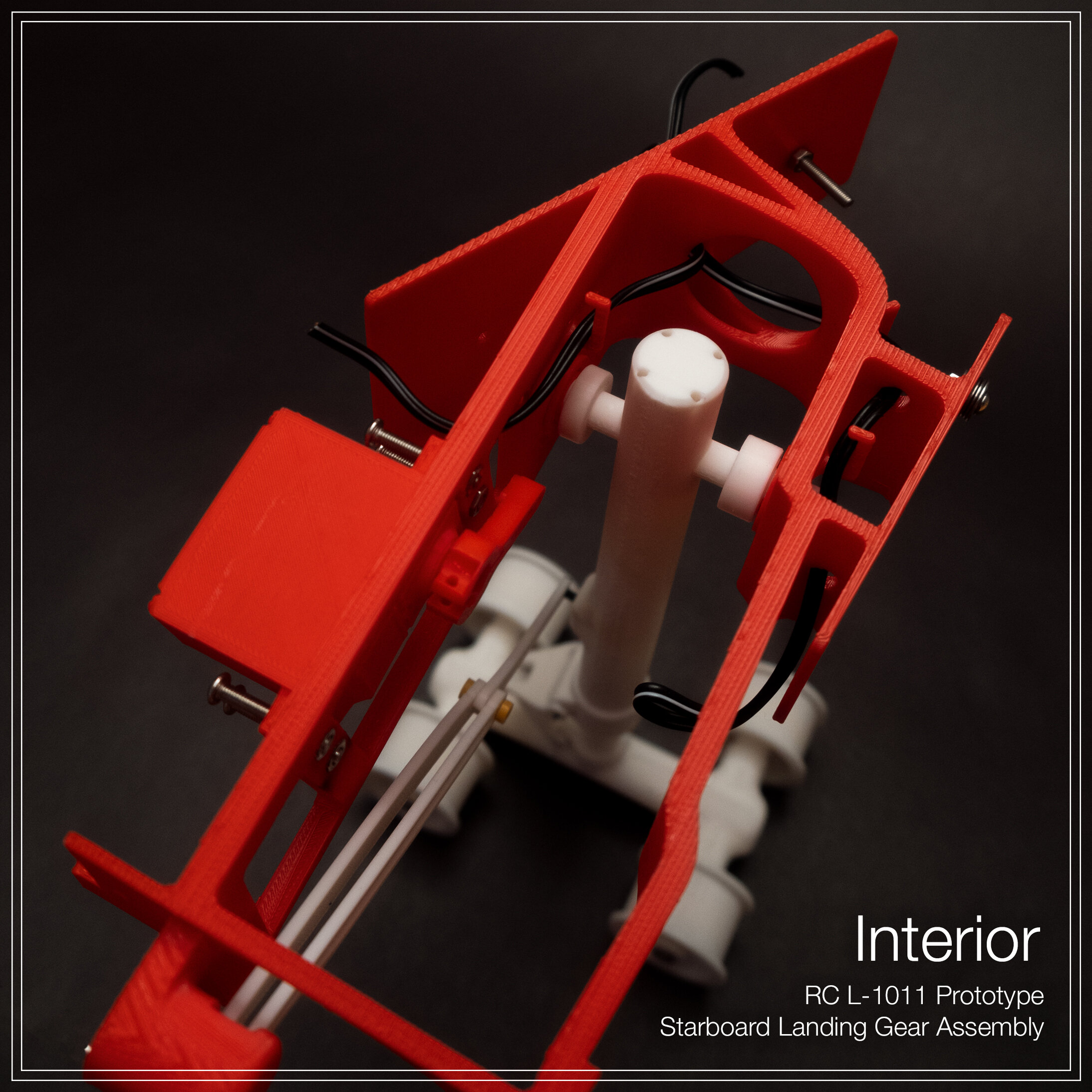
Interior Landing Gear Housing and Mounting Bracket
Looking down into the gear support structure and housing you can see black wires. These are to check for clearances and routing of wires to ensure they do not rub or catch on any moving parts.

Retracted Landing Gear Top view
Looking straight down on the gear assembly, this shows how it looks in the fully retracted position. The right wall of the housing is the root of the wing mount, everything right of it will be inside the fuselage.
As I continue working on the landing gear, I will be posting updates to this post with more photos and diagrams. Follow me on IG and Twitter if you are interested in regular updates and progress on this build.