
How to Calibrate (Scale) Canvases in Fusion360
This is a follow up video to "How to Design a RC Airplane". In this follow-up I give more detail on how canvas calibrations in Fusion 360 are done. You should have watched the previous episode or have a basic understanding of Fusion 360.
In the previous episode we I went into detail on how you can start designing for a scratch build airplane with F360. At the end of the video we had the beginnings of the fuselage of an airplane design. The part covering canvas placement I moved quickly through placing 3 diagrams on construction planes, however, for some it was not enough detail in how to go about actually scaling the diagrams.
“Once you’ve completed this tutorial you will know how to scale, calibrate, any diagram”
This supplemental episode addresses this oversight in a five and half minute tutorial. Although geared towards RC airplane designers, any CAD designer whose using Fusion 360 and does not know how to do calibrations this video should help.
Once you've completed this tutorial you will know how to scale, calibrate, any diagram so that your designs are at the exact scale you intended. I chose millimeters as my units of measure, but you can choose between metric or customary unit such as inches. Any of these will work for whatever fits your design preferences or requirements.
Follow Along on your Favorite Social Media Platforms
Calibrating Fusion 360 Canvas Diagrams Steps
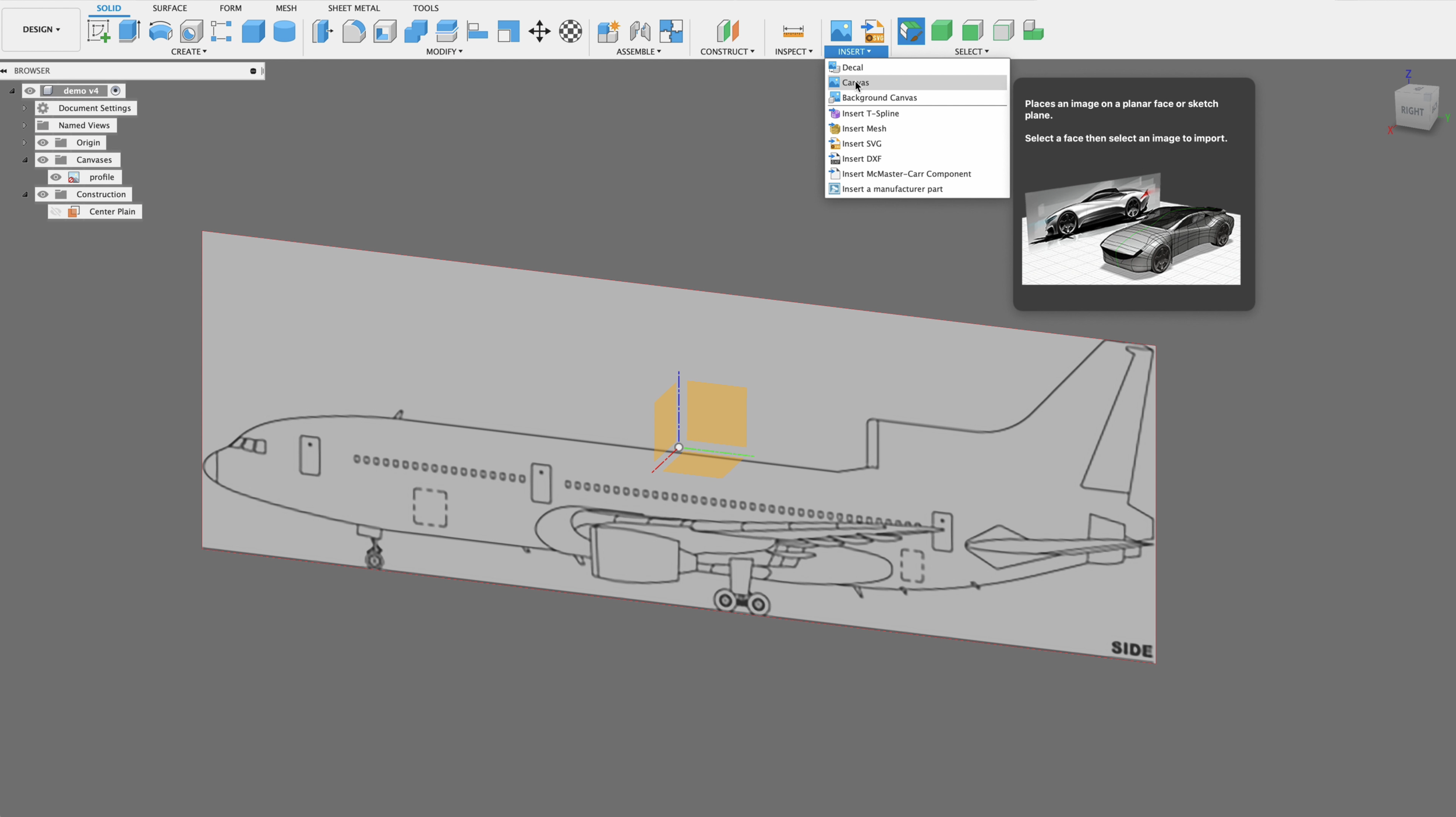
Diagram Canvas Placement
Start by placing all of your canvases on the three planes. To do this select “Insert - Canvas” from the tools tape at the top of Fusion 360. Then choose the files from your computer, then select the plain in which to place your diagram.
Repeat this for all of the diagrams you need to place for the different orientations.
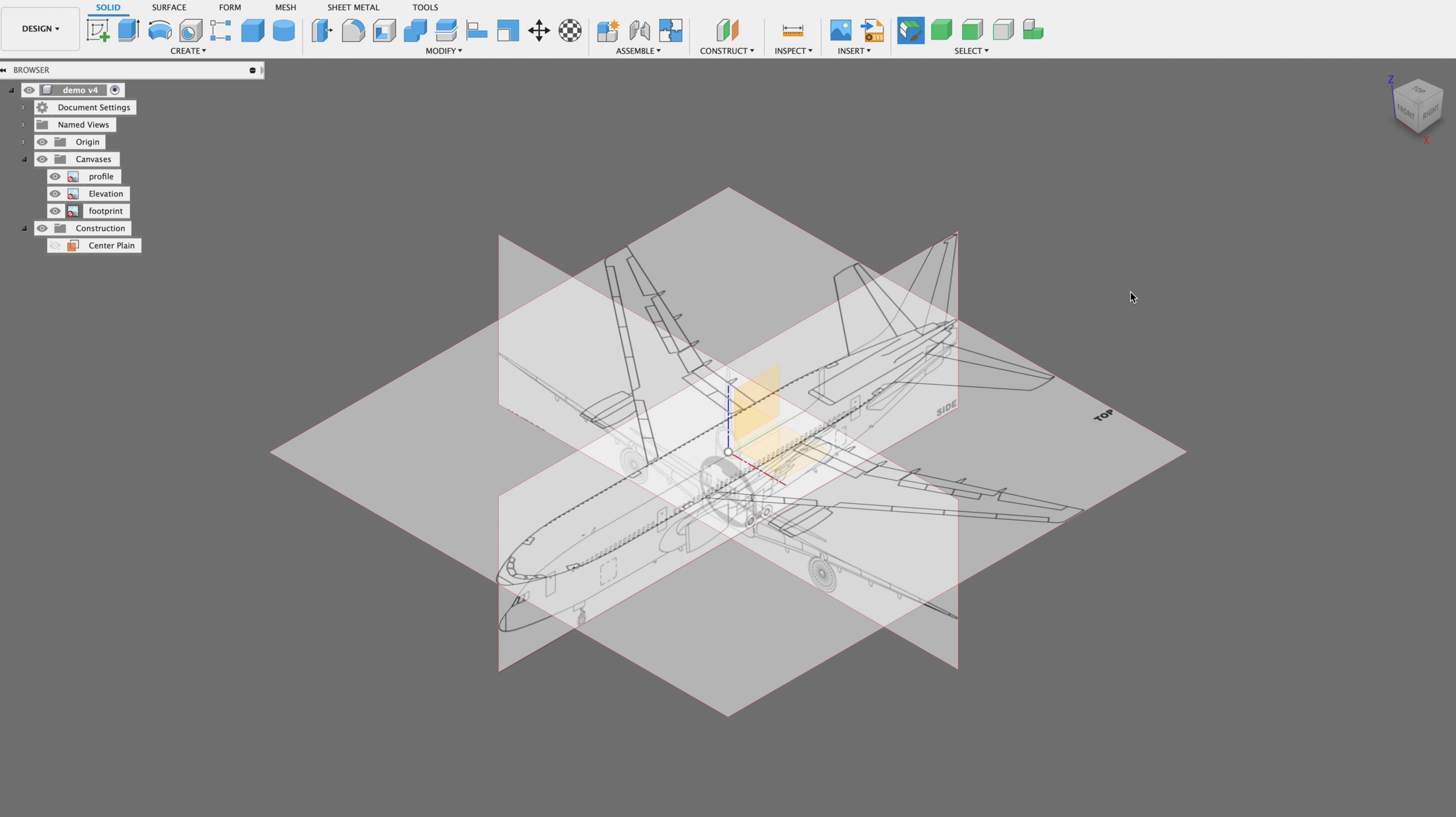
3 Views in Place
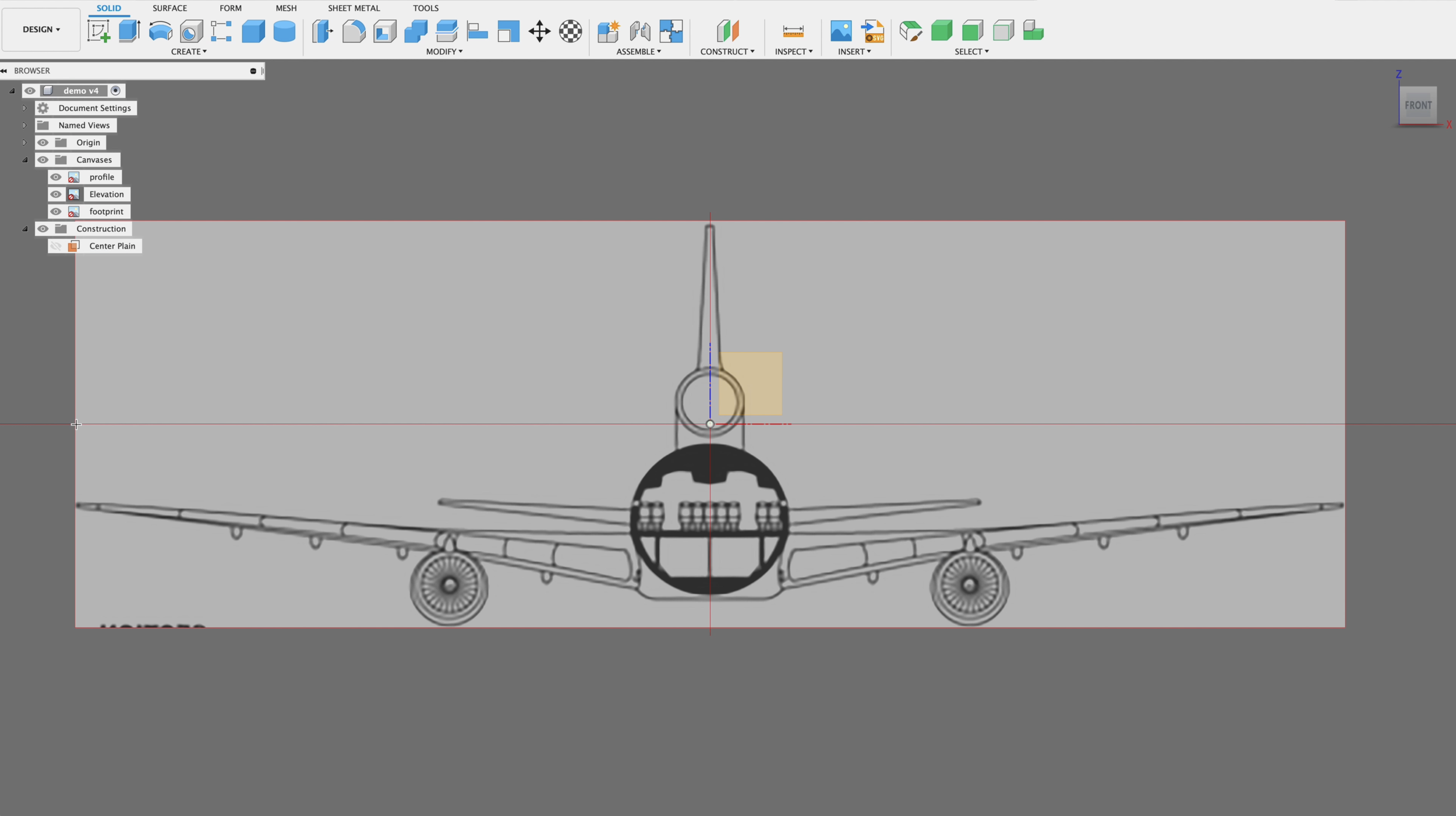
If you are working on an RC airplane design, you should have all three perspectives placed as canvases.
You should have a footprint, a profile view, and a front elevation view. In this example they are all centered at the origin point of our workspace.
Determine Scale
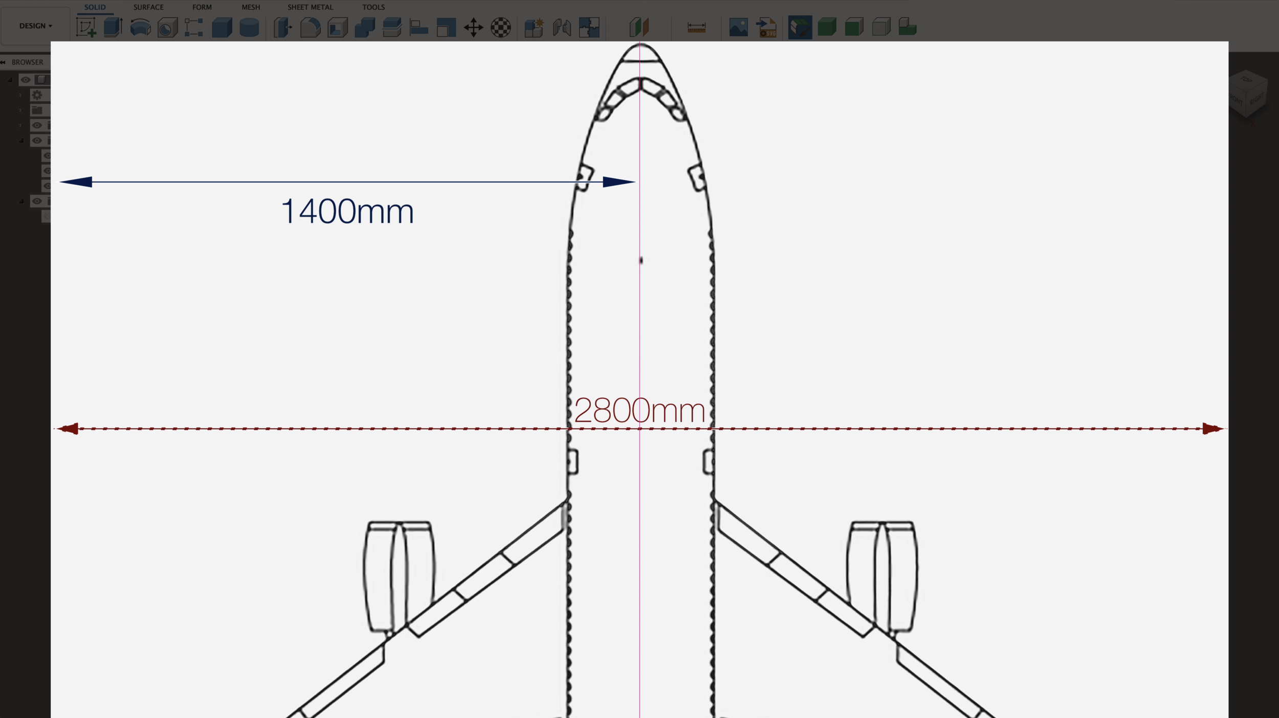
Before you begin scaling your canvas (Diagrams) It is important for you to decide what scale you are working on. In the example of L-1011 Airliner I have chosen a 1/20 scale. I will use the centerline and divide the total wingspan by half.
The reason for scaling from the center pointe instead of canvas sides is because the canvas might not be perfectly centered, or cropped. Doing it this way this ensures that our scale will be accurate from the centerline.
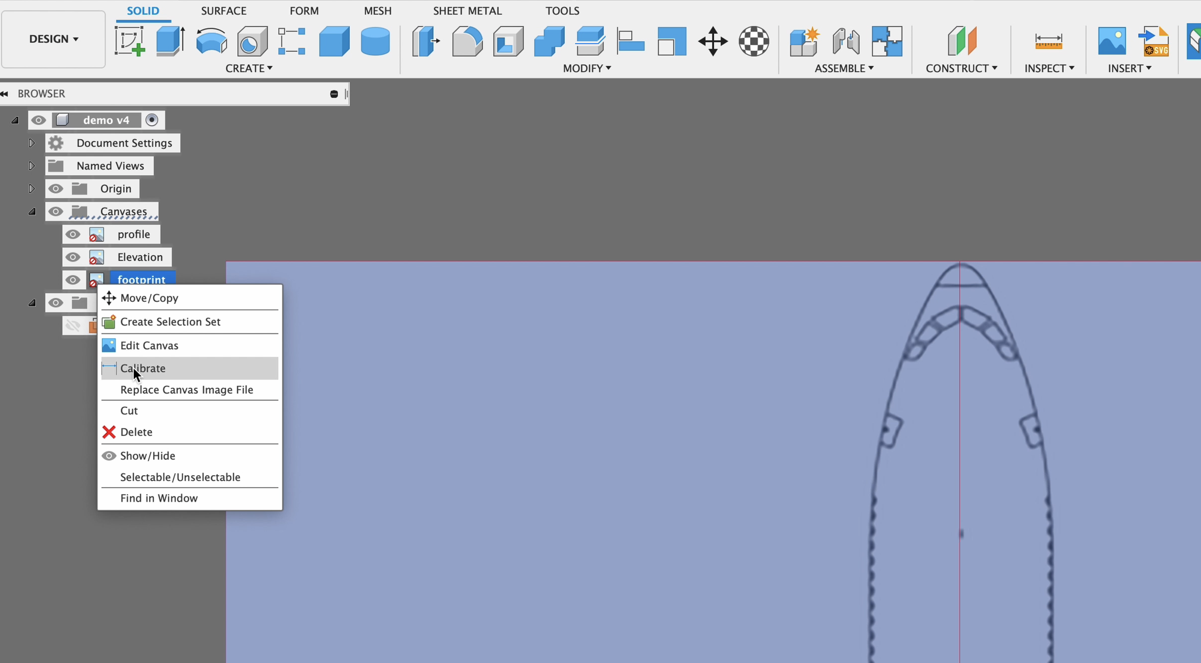
Begin to Calibrate Canvas
Once you have your scale decided, go to the Fusion 360 browser, scroll down to the canvas, in this example we’re going to scale the footprint first. Right click on that canvas and in the popup menu select “Calibrate”.
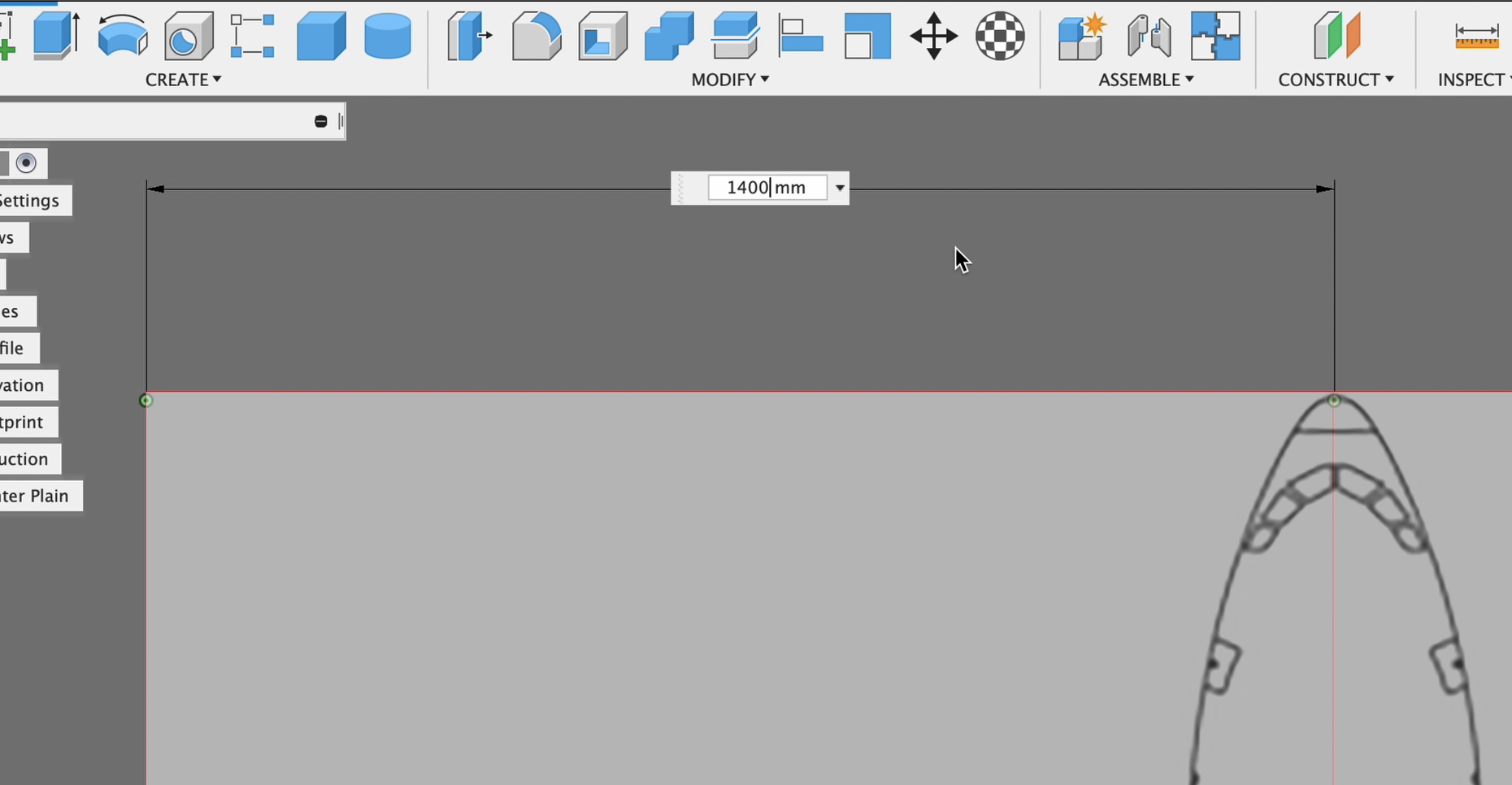
Place Start and End Points
Move the cursor to the nose of the aircraft or wherever your center point may be and click to mark the start point. Then moved to the edge of the canvas, in our example where the wingtip edge is, Then click to mark the end point.
NOTE: It's important to note that you do not place your points at an angle from each other. Do you want to make sure that they are parallel and on the same horizon.
Continue…
Repeat this process for all of the views you have.
Manual Canvas Calibration
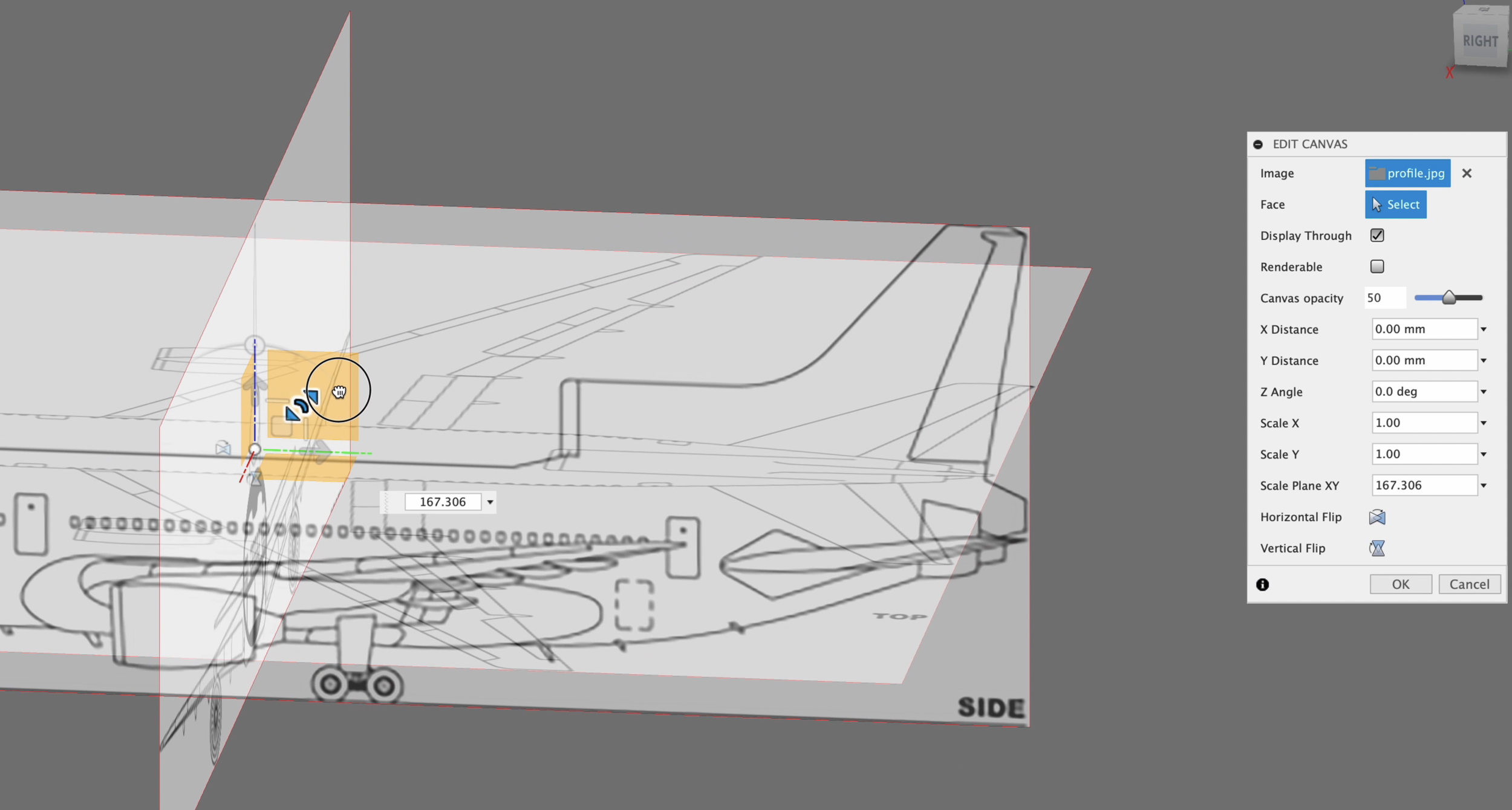
If you run into a situation where a canvas does not align correctly with your other canvases, you may choose to manually adjust the calibration.
To do this you will need to right click on the canvas in the browser, and select “Edit” from the drop-down menu. Then you can use the handle as pictured to pull your canvas to the correct size. You may also manually fine tune Chi Chi any numbers into the scale input box.
Episode Outline
0:00 Introduction
0:32 Make Sure You've Set Preferred Units of Measure
0:42 Placing Diagrams as Canvases in our workspace
1:30 Changing Canvas Orientation
2:00 Deciding your canvas scale
2:18 Precise Canvas Calibration
4:05 Manual Canvas Calibration /Manual Scaling
4:52 Final adjustments and positioning