
Part 1: Design a RC Airplane Wing in Fusion 360 (Airfoils)

Episode 2.1 - Setting Up Our Workspace to Design a Wing
In this Episode, you will build upon the concepts and tools introduced in episode 1 - “How to Start Designing a RC Airplane”. You will continue from where we left off with the center fuselage started in episode 1. I’ll guide you through the process of how to set the foundation for your RC Airplane’s wings using Fusion 360.
Airfoils
To get started, we will need to choose airfoils for out wing design. In the case of the L-1011 that I am working from, I have chosen airfoils for the wing root, mid-wing, and wing tips. The reason for this is because this airliner has a blended set of airfoils from the root to the wing tip.
Additionally, the wing is twisted, which is referred to as washout. I have added a small description below with a link to more information about this design consideration.
To start choosing your airfoils, I would recommend visiting airfoiltools.com and selecting an airfoil there. I would discourage you from hand drawing or creating your own airfoil at this time and use a known and tested one from the airfoil tools website. All of the information you’ll need for any given airfoil will be available on that site.
When designing your wing you want to have semi predictable results and flying characteristics depending on your requirements or handling profile.
Cl v Alpha Chart
As I’ve noted, for my RC Airliner, the L-1011, I’ve chosen three airfoils. Two of which are the NASA CS(1)-0614 Supercritical and Curtis C-72 High Lift Airfoil. The airfoil at the wing’s MAC (Mean Aerodynamic Chord) is a transitional airfoil that blended well between the two different AFs
The full scale plane used a supercritical airfoil at the root and twisted to produce washout at the wing tips.
Since I was unable to find actual technical information about the wing design and the specific airfoils they used to develop the L-1011, I had to approximate which AFs to use.
To come close to this design, while also having a flight characteristic I’d prefer in my model, I pulled several airfoils and worked on blending them.
It took 3 or 4 complete wing design iterations to finally settle on one which you can see in my current design.
Be patient as you work through your design.
I can’t stress that enough. Wings are difficult to design and there’s a lot of physics and theory in this specific topic. Most of us are hobbyists, without a degree in aeronautical engineering or with a deep understanding for fluid dynamics, can fully understand or appreciate the intricacies and study that goes into efficient, predictable wing development. Nor do we have wind tunnel facilities to test our wings in the most nuanced and precise ways available to the pros.
Take your time, learn to read Lift Coefficient v Alpha charts and you will be fine.
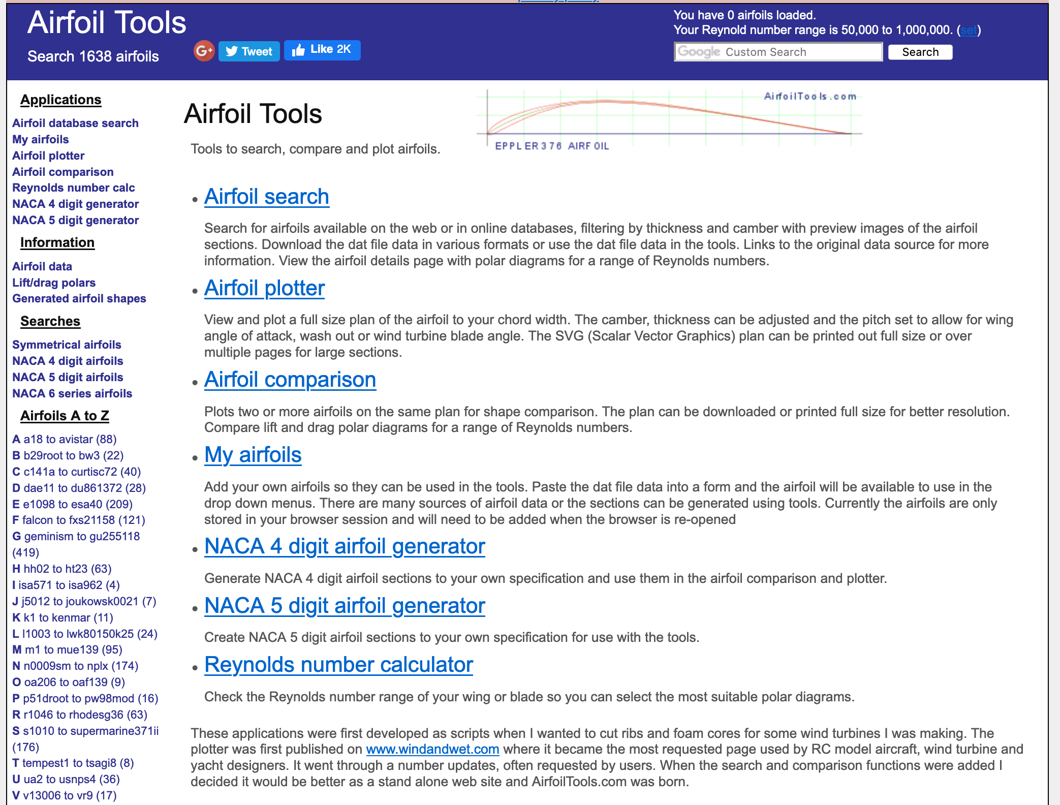
AirfoilTools.com Screenshot
That being said, you’ll need to have a general understanding of the wing you are attempting to replicate in your flying model. Analyze and do your homework on the original aircraft you are trying to replicate as you incorporate your chosen airfoils into your design.
I used airfoiltools.com to search for airfoils and after several days of searching, modeling and swapping out airfoils, I settled on the 3 different airfoils.
For this tutorial I have used the following two airfoils. You may choose to download them or select your own for your design.
How to Download Your Own Airfoil DAT File
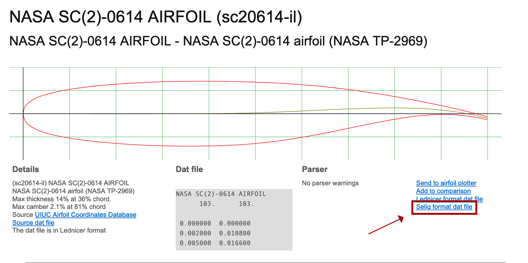
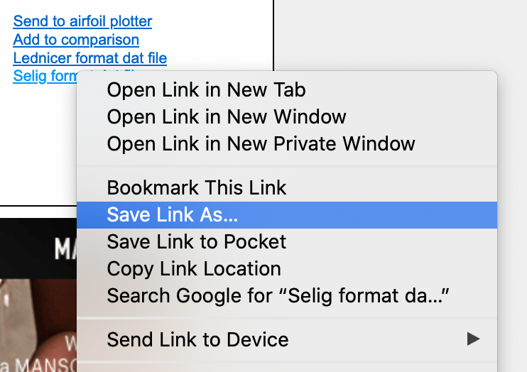
When you have chosen an airfoil you’d like to incorporate in your wing simply click on the link titled “Selig format DAT File” .
Refer to the screenshot here to quickly locate the link.
When you click the Selig format DAT file, your browser will most likely display the contents of the file without prompting a download box. There are two ways to solve this.
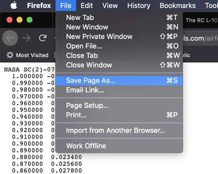
Option 1
Click the link, which will display the contents of the file in the browser window. Then, in the main browser menu click “File” then “Save Page As” or “Save as”. It will depend on your browser.
You will then get the save file prompt. Save the file as “airfoil_name.dat”
Option 2
Instead of left clicking, on the Selig format DAT file link, right click the link to get the options dialog menu and select “Save Link As”.
Then select a location on your computer where you will be storing all of your airfoils.
That’s it. You now have your airfoil.
Wing Washout - What is It?

Washout is when a wing is twisted along the length of the wing, where the wing tip’s angle of incidence is angled a certain amount of negative degree(s) in relation to the wing root. Read about why wing washout is important by click here.
Step 1 - Setting Primary Airfoil Construction Planes
Once you have the Airfoils script installed and have restarted F360, it’s time to get started with the first step. We need to set up our workspace in order to place the airfoils into our design. For this tutorial we are using 2 airfoils as an example, but in my actual model of the L-1011 I used 3 airfoils. This is a design decision I made to improve the lift capability of my wing near the engine nacelle. It is also the place where the trailing edge changes angle.
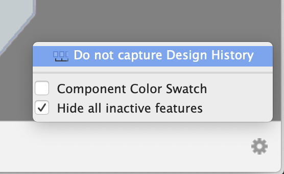
Important (Can’t Rotate Construction Planes?)
If you can’t rotate construction planes, this is an indication that you are in parametric modeling mode. You must turn this off by right clicking on the top component, and turning off design history. Alternatively, you can use the gear icon in the bottom right of your screen on the timeline and turn design history off there.

Begin by placing the first construction plane. The first one is going to be located at the wing root. To add the first construction plane, click on construction, then select the Z,Y axis plane at the origin. This will create a construction plane on top of the origin plane.

At this point you can resize the construction plane (CP) and move it into position where you will add your root airfoil later. A quick tip, the keyboard shortcut key for the move tool is the letter “M”. This will give you the moving Triad at the construction plane or the body’s origin point.
Before you continue on to the next CP placement, you need to orient your workspace to the top view so that you can see your footprint diagram. You will notice that your CP is in the center of the fuselage. That’s not where we need it to be. It needs to be moved to the very edge of the fuse where the wing will be mounted to the airplane.
Now that you have your first CP in place, it’s time to move on to the next. This one, however, we are going to place at the point where the trailing edge changes angle near the engine nacelle. It is very important that you place a CP at this point. If you don’t, you will end up with a very strange cutting body later on.
Lastly, create and place a 3rd construction plane near the very tip of the wing. Notice that we do not place it right at the edge. The CP is positioned just ahead of the leading edge curvature.
Step 2 - Adding Airfoil Splines (As Sketches)
Now it's time to introduce our first airfoil into our workspace.
Before we get too far ahead of ourselves, there's a little hack that will help in this process. Since it’s not possible to measure the chord at the wings root using the built-in measure tool, we need to use another tool in order to get the length between the trailing edge and leading edge.
Using the box tool, you will notice when you span the chord at the wing route, that the measurements of the box appear and the width will already be highlighted. Once you’ve positioned your box points at the trailing edge through to the leading edge, copy the width by pressing “Control + C” or “Command + C” to copy that dimension.
You will now have the chord on your clipboard.

With that little hack out of the way, we will use the Airfoil DAT to Spline tool. To activate this tool, you will need to hold down the shift key and then press the letter “S” (Shift + S). This will activate your add-ins and scripts pallet.
You will see the Airfoil DAT to Spline tool under the scripts section. Double tap this script and it will open up the airfoil parameters pallet.
Where you enter the cord measurement delete what's in the field currently, and then press command V or “Control + V” to paste the dimension that we copied from the box tool. Doing it this way ensures that our court will be the exact length we need for our route airfoil. Next we make sure that the select button is highlighted in blue then select a route construction plane that we placed in step one. Then press “OK” in our “Airfoil Parameters” pallet.
You will notice that the CP will disappear, and you will not see the airfoil sketch appear. Don't worry, this is a strange behavior within the script. If you zoom out far enough you will notice that the airfoil actually is within your workspace, it’s just not where we would like it to be. Simply zoom out until you see where it is in your workspace and move it into position.
Do not be tempted to move the airfoil sketch by the X axis. It is actually on the correct access at this time. All you need to do is move the Y axis and the Z axis into position.
Use all of your views to make sure that you have placed it correctly on the Y axis and that you have placed it correctly on the Z axis.
In the video tutorial, you will notice that I angle my route airfoil a positive 1.5°. I chose to do this after reading the coefficient of lift versus alpha chart. This chart indicates that a 1.5° positive angle of incidence will slightly increase this airfoils lift capability at 0° angle of attack. For example when going down a runway.
Repeat this step again, this time for the center airfoil. We're going to use the same airfoil as the route, however this one we are not going to angle we will leave it at 0°.
Lastly, we will pick our wingtip airfoil, and place it on the third construction plane. You will notice that this airfoil within the video tutorial I actually angled the angle of incidence by -3°. This is done for washout.
In the video I provide a small talk about what washout is, and why it's important, and why you should definitely include it in your design. Especially if you were designing a swept back wing for an airliner.
Conclusion
Although this was only two steps the set up process and getting our main airfoils in place does take some time. He requires doing research, learning how to read a Coefficient of Lift v Alpha chart and choosing your airfoils. It is important that you do a little bit of research for the airplane that you're wanting to design. Some might have the information readily available about what kind of airfoils were used in the actual aircraft, however, this is usually proprietary so you will have to approximate which airfoils to use if you're wanting to be true to scale.
In my wing design, I was able to find references to supercritical airfoils being used on the L-1011. This became my starting point. Then looking at the wingtip and noticing that it was not a super critical airfoil, I was able to select another airfoil. Since this is an RC airplane I wanted to increase the lift capabilities of the wing to give it a more docile behavior. And for this reason I selected the Curtic-C airfoil.
If you have not already, please subscribe to the YouTube channel so that way you are notified of new videos and when part two of how to design an airplane wing in Fusion 360 is released. Also, if you feel so inclined consider leaving a tip or snagging some swag to help support this website and YouTube channel.
** Many of the concepts in this episode were covered in “How To Start Designing an RC Airliner“. If you have not already watched that video. It will help you set up your scaled diagrams needed for this episode.
Episode Outline
0:00 Introduction
0:40 Thank You Tip-Jar Contributors!
1:40 Before you Start, Install Airfoil DAT to Spline Script
2:32 Step 1: Placing Construction Planes
10:37 Adding Airfoils to Construction Planes
18:46 Break & Reminder to Subscribe
19:18 Airfoils 2 & 3 Placement
23:54 Wing Washout and Why It's Important
26:21 Closing Incomplete Airfoil Splines