
Part 3: Design a RC Airplane Wing in Fusion 360 (Slot & Tab Joints + Wing Mount)
Episode 3 - How To Add Spar Caps, Rib/Spar Joints and Wing Mounts
In this episode, we wrap up the wing design series. In parts 1 and 2, we set the foundations for our wing, now we’ll cover the last of the details which include adding slot joints, tab joints, rod-type wing mounts, and how to lighten the weight of the wing through rib trusses. If you haven’t completed the work from that previous episode yet, you’ll need to go back to “How to Design a RC Wing in Fusion 360” part 2. This guide is to supplement the included YouTube video tutorial.
The work that we will be doing in this tutorial is geared towards modelers who will be building their airplane out of wood, carbon fiber, or foam board, then cutting the pieces out with a CNC machine, laser cutter, or hand cutting from printed diagrams. 3D (additive) printing involves other steps which are not covered here, however, many of the design concepts are the same.
First, Create a Dedicated Nose Component
Before we beginning, its a good idea to create a dedicated component group for your nose. To create that component, simply right click on the root component in the component tree and select “New Component”. While naming the component, check the “Activate” checkbox so that when we click OK, the component will automatically be the active component.
The benefit of activating a component ensures all of the bodies, construction planes, sketches, forms, and surfaces you create will be added to the active component.
Now that we have the nose component, it’s time to get started.
It’s good practice to go through this extra step to keep things nice and tidy. Keeping our workspace organized will help us better manage our design as it becomes more complex with more parts, construction planes and sketches. It will also save you time later in this series when we move to the manufacturing stage of our airplane.
Spar Caps, What are They?
In aircraft, spars transfer the many forces encountered by the wings throughout the airframe. Spar caps provide the spar web(s) lateral reinforcement and rigidity much the way an I-Beam does in building construction. Depending on your design, the loads are transferred directly into the airframe, or into the wing box to which the body is attached. The forces spars must resist include the bending, which is composed of tensile, compressive, and shear forces. The spar must also be rigid enough to restrict torsion induced by aileron and flap deflection.
Due to all these types of forces, a spar must be strong enough to absorb and transfer these loads. In our current design, we have a single flat surface also known as a web. That web alone cannot resist those forces especially as the scale of your model airplane grows.
For example, a RC plane that has a wingspan of 100cm will encounter, by many magnitudes, far less arrow dynamic forces than a model airplane that has a 300cm wingspan. The orders of magnitude are cubed. This means 1 cubic centimeter of volume doubled is 2 cubic centimeters but will have 8 times the volume.
Due to these multiplying forces, we need to reinforce the web with spar caps.
Spark caps, for RC airplanes, can come in many different varieties. For smaller airplane spar caps might not be necessary as you can use a thick enough web and be fine; but for the model that's being demonstrated extra reinforcement is needed. In this demonstration we will be adding a single spar cap on the interior of the forward bar.
It's important to note that material choice also has a large bearing on the spar design. Carbon fiber spars for instance are far more rigid and strong than Balsa spars. If you have any doubts as to the rigidity and strength of your spars adding spar caps is strongly recommended.
Steps to create a spar cap

Orbit around so that the interior of the forward spar is visible. Using the sketch tool create a sketch on the interior surface of the spar. Once the sketch tool is active we need to create a projection. The projection will ensure that the top edge of our spar will be perfectly aligned to the spar web.
With the projection of the spar we now have in our current sketch, we need to use the offset tool to offset the top line and pull it down to a distance that is appropriate for the design.
The offset provided an identical template, however, it is smaller than the exterior outline. We need to add a spline to divide the top end which we will use as an extrusion.
Once you have the spar cap defined, you can use the extra tool. Extrude the spark To the thickness of the material you intend on using. Double check that you are creating a new body when doing the extrusion. It can be very easy to overlook that setting and accidentally create a join.
That's all there is to it. There's no further work that we need to do with this spar cap.
Spar/Rib Slot Joint
From episode two when we implemented our ribs and spars, we can see that the bodies actually enter into one another. This is not how we need to construct them. For this reason we need to add joints. For this demonstration I will be showing you to joining methods for your ribs to spars. The first method will be the slot joint the second method will be a tab joint.
As with most things, many of these are design decisions that you will have to make. For learning purposed I want to show you a way that you can implement these two common joining methods with Fusion 360.
Steps to Create Spar and Rib Slot Joints

Orbit your workspace until the forward facing spar is visible.
As we did in the previous section, we will be using sketches. To create a new sketch, select the sketch tool and then press the forward facing spar web. Next, we need to use the intersect tool to transfer the intersecting body faces. We will do this on both sides of each rib where it crosses the spar. It is recommended that you do one side at a time to make it much quicker, then orbit so you can see the other side of the red and intersect each of the opposing sides onto the sketch.
Once you have all of the inner sets projected onto our sketch, you will create a horizontal cross about midway between the top edge and the bottom edge of the spar.
Hide your ribs component group, we don’t need them for now and they will just be in the way of the next step.
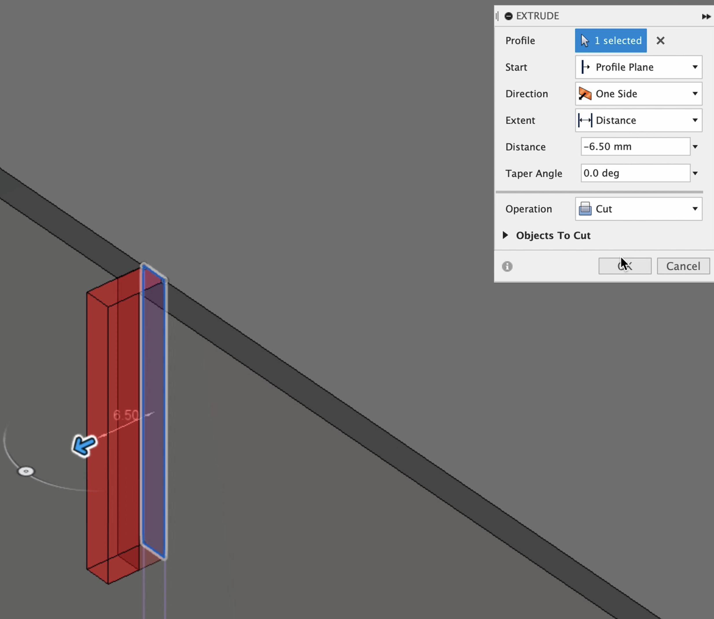
Now we will use the extract tool again, this time we will use it as a cutting tool. Select one of the faces of the sketch, press the “E” on your keyboard, or select the “Extrude” tool out of the toolbar. Then push through the spar. You will know that you are cutting the spar by the read transparent extrusion area. Select ok, and repeat for each slot.
Re-enable the ribs component.
Having created the slots on the spar, we can use those as the template for removing the overlapping body areas in each rib. To do this we will use the “Combine” tool.
Activate the “Combine” tool and select the first rib which will be slotted, then in the “Combine Palette” ensure you have “Cut” operation selected in the drop down setting. Make sure the “Keep Tool” checkbox is checked and the “New Component” checkbox is NOT checked. Next, activate the tool bodies box in the pallet. Once activated select the spar as the tool and press ok.
To verify the rib now has a slot, use the move tool, or isolate the ribs. If you notice that a portion of the rib was not fully removed along the edge. You will have to remove it. To remove it you can use the “Push Pull” tool, the “Extrude” tool or you may use another body, such as the spar as a cutting tool. Any way works.
Repeat these steps for each rib.
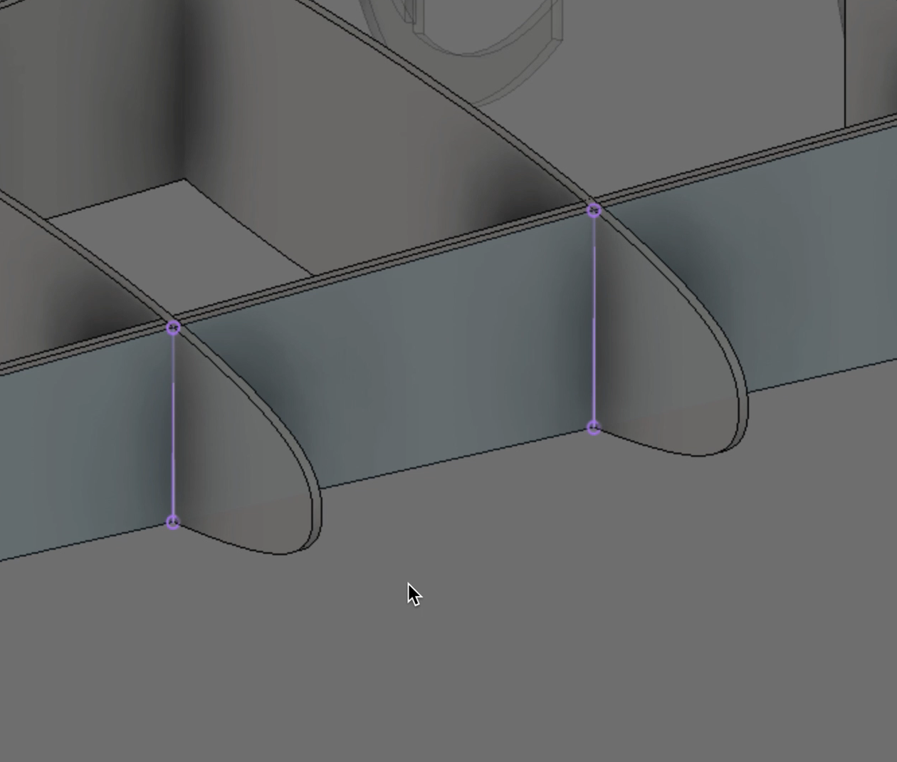
Spar/Rib Tab Joint

Tab joints are as they sound. Tabs that insert themselves into the spar. This joint is pretty straightforward to create. Using the following steps, you will create tabs for your ribs and cut the tab holes in the spar.
Isolate your ribs. Then select your first rib, and activate a sketch on either side of the rib. Using the rectangle tool, draw a rectangle near the trailing end of the rib.
Once you have the sketch completed, use the extra tool and push into the rib. Ensure that the join operation is selected in the extrude palette. Then pull the rectangle out of the trailing edge of the rib. Ensure that your extension extends all the way through the trailing spar.
Repeat this step for each individual rib that is to join with the trailing spar.
After that has been completed, you may use the combine tool to cut out the tab holes from the spa.
Wing Mount Rods
There are countless ways to mount your wings to your RC airplane. Some build a Uni wing we're both wings are connected to the wing box. Some build a central wing box with rods or spars that enter and fastened with screws.
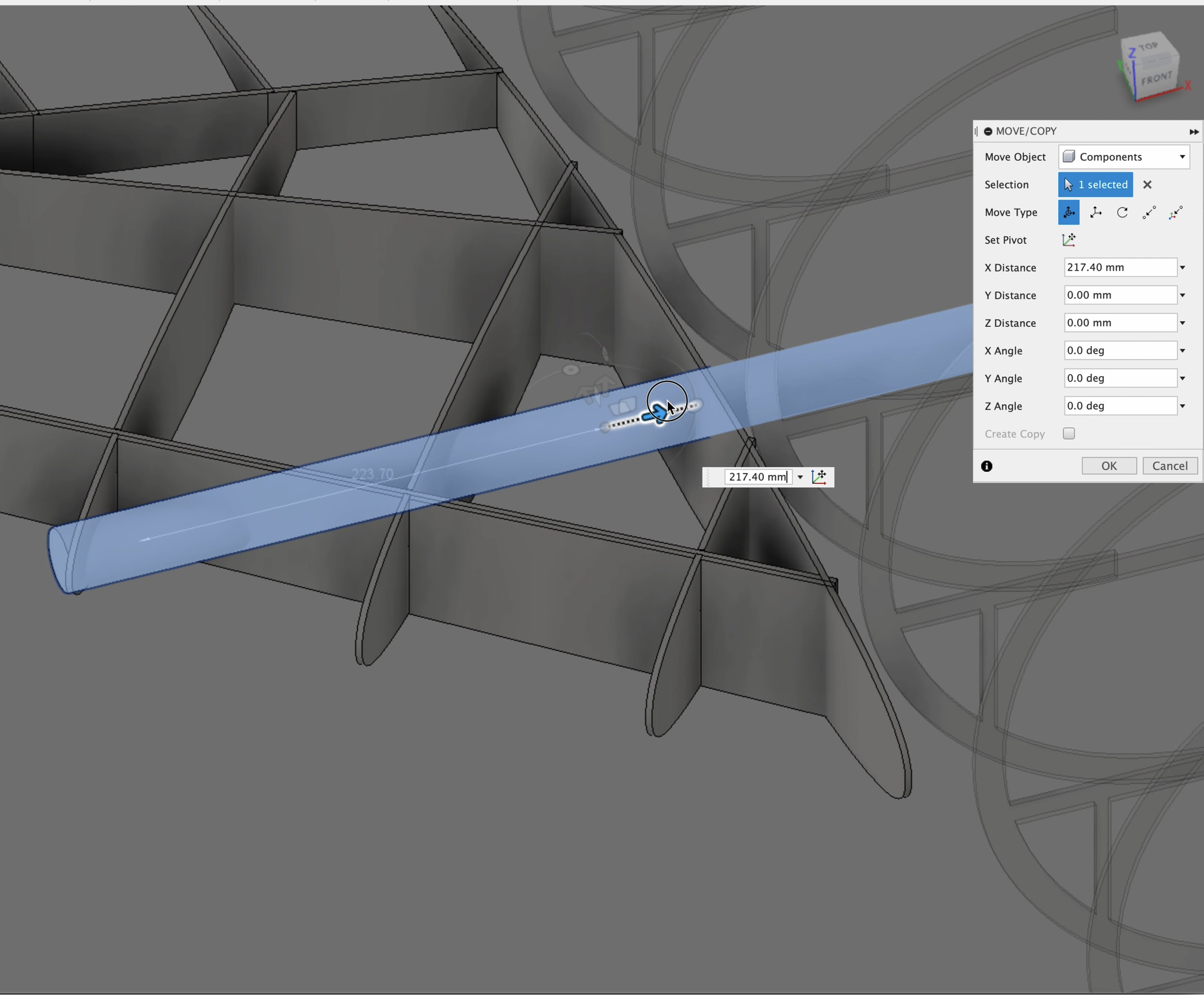
In this example we will be using the rod style wing mount in method. To do so you only need to use the cylindrical body tool. Ensure you have the wing root base plate in place. Then create a cylinder to the size of the rod that you'll be using. Then from that surface create a rod that enters into the wing. Then reposition the rod as needed.
Once the rod has been positioned, then you can use the combine tool using the cut operation to remove the material from the wing ribs to accommodate the position of the rod.
It's really that straightforward.
Wing Rib Types
The final process is to remove material from the ribs in order to lighten the overall wing. Depending on whether your rib is structural or simply a form to shape the wing’s skin. This will determine how much material you remove, if any.

In this tutorial, you will be creating a truss type rib. To do so you will use the sketch tool once again.
Select the first rib using the sketch tool then draw 45° lines against the surface of the rib.
Once you have designed the position of the trusses, use the offset tool by pressing the letter O or selecting offset from the toolbar. Then select how much material you would like to have in the truss.
upon completion of the design of the truss use the extra tool to cut into the rib removing the material. And just like that you now have a trust type rib.
Conclusion
In this episode, we completed the primary design of our wing. The key of this set of tasks was to reinforce and strengthen the spar's. The aim is to remove torsion caused by a Laurent and flap to flexion. Additionally we provided lateral support through the spar caps.
Next we created the joints to attach our ribs securely to the forward and trailing spars. We did this with two types of joints, the slot tape joint, and a tab tight joint.
Based on the scale of your airplane the spars, and how they are designed, become more critical the larger your plane gets. This is due to Square cube law.
We also added mounting rods. This is how the plane’s wings will be attached and secured to prior to flight. Additionally we removed material from the ribs in order to lighten the overall weight of the wings and ultimately the plane.
If you have any questions or need additional help, please contact me through the website or DM me on any of the social media accounts I have listed here.
Until next time, happy modeling.
Episode Outline
0:00 Introduction & Thank you Eli DElia
1:07 Create Dedicated Wing Component
3:46 Create Spar Caps For your Spar
10:41 Rib Connection With Slot Joint - Forward Spar
21:35 Rib Connection with Tab Join - Trailing Spar
25:31 Wing Mount Rods
31:40 Lighten Wing Weight with Truss Type Ribs
35:01 Wing Box / Wing Root Abutment Formers
43:44 Thank you & Outro