
Model an Airplane’s Tail Section in Fusion 360 - Vertical & Horizontal Stabilizers.
Episode 6 - Using The Sketch & Loft Tools To Model the Tail (Empennage) Section of an Airplane
Welcome to the next tutorial in the airplane design series from RC CAD2Vr. In this tutorial we will be completing the primary structure of our plane’s fuselage; the empennage, also commonly referred to as the tail. This is the most complex part of the design phase due to the many angles and shapes we need to create. It may look deceptively simple, but there are many things to consider and specific steps to take as we complete the body of the airplane.
What is an Empennage?
In conventionally designed aircraft, the empennage is often referred to as an airplane’s tail. It contains two critical flight control surfaces. The left and right elevators are attached to the trailing edge of the horizontal stabilizer and the vertical stabilizer, or tail fin, where the rudder is attached to the trailing edge. In some aircraft, the horizontal stabilizer is a stabilator where the entire surface moves instead of just the elevators. These control surfaces control the yaw and pitch movements of the airplane.
Structurally this is an interesting section of the airplane as the forces it can induce on the airframe can be great. Also it is the most narrow portion of the airframe. Depending on the design of the plane, its moment can also be pretty far from the center of mass.
When designing your plane’s empennage, it’s important to consider how you will ensure the strength of the structure. Carefully think about how to design these components so that the load paths are carried into the airframe to ensure maximal strength and minimal weight.
Special consideration should be made at the connection points of the stabilizers. They need to be designed in such a way that they can easily absorb and transfer torsional, tensile, compressive and sheer forces. Remember, the faster your plane flies and the bigger your plane is, the greater these forces become.
Before Starting
This tutorial builds on all of the previous airplane design tutorials. If you have not completed the “How to Start Designing an Airplane in Fusion 360” Tutorial, some of the steps in this tutorial will not be possible. I encourage you to go back and build the components we will be building in this tutorial.
Organize your Component Tree
In his first step, we're going to create a new component called “Tail”. Make sure that you also activate the components so that all of the work we do will automatically fall inside of the component.
Projecting Center Fuselage Formers
As we have in previous episodes, we need to project our central fuselage formers onto a construction plane which is within our active component. To do this, we need to activate the center fuselage section. Then we will create a construction plane on the surface of two of the formers. Our formers have slightly different shapes, due to the wing box versus the cylindrical shape of the primary fuselage. For this reason we will project both formers into our current component.
In order to also design the fairings which create an arrow dynamic transition between the wing box and the empennage, we need to also create a second sketch which is identical to the cylindrical shape of our fuselage. We will use both of these projections to ensure we have a nice transition.
Sketch the Spines
The spines will be the top ridge of the fuselage and the lower, or belly, of the fuselage. The spines will serve as our sketch rails when we get to the point of lofting our fuselage. For now we will be sketching in three parts; the tail edge the top ridge and the bottom ridge.
To begin, we need to turn on our canvas so we can use them as a guide for the shape of our fuselage as we did in previous episodes. For this tutorial, we will only need to use the profile view and the top-down views.

Next activate your center construction plane. The center construction plane should be in our root component from previous tutorials. Once visible, start a new sketch on that construction plane. Once that's active and ready to go, we need to project the former points of the top and bottom ridges onto our sketch. Now that we have those projected, we can begin drawing our top spine.
Using the line tool snap to the first former, then to the second former’s projected points. Switch to the fit point spline tool and sketch the top ridge of the fuselage. Except the line by clicking on the check-mark or press escape. Now, we will repeat this process, this time for the lower spine. Once we have those two spines, connect them at the rear of the airplane.
Horizontal Stabilizer Mounting Surface
An airliner’s fuselage is cylindrical, however the mounting surface for the horizontal stabilizer needs to be flat. In order to accommodate this we need to sketch a few construction lines that we can use as guides to ensure we have a flat surface where our stabilizers will attach, while also maintaining smooth transitions.
This will be the first time in this series that we use construction sketch lines. They are very simple to use and very handy.
Start by creating a construction plane on the YZ axis. Then move the construction plane into position where it appears flush against the fuselage where the horizontal stabilizer will be mounted.
Important: Ensure that you are in the direct design mode and not in parametric design mode. You cannot rotate construction planes when in parametric design mode.
Once you have the construction plane positioned, we will create a new sketch on it. In the control pallet look for the icon with the label “Construction”. It should be the very first option in the most recent version of Fusion 360. Click the icon to activate it.
Any line you create while the construction is active will create lines and splines that are dotted, indicating that they are construction sketch lines.
The Stabilizer Cross
Since we have a surface that is going to taper towards the end and is round it off, what we will do is create a cross where the horizontal stabilizer will be attached. This cross will serve as a flat surface that we can transition between curved surfaces and the flat surface of this mounting area.

Another aspect is ensuring that our fuselage surface also accommodates the transition to the flat surface of the mounting area. To accomplish this we need to add additional construction lines that go from the forward point of the cross to the midpoint or the widest point of the forward formers.
To easily find the widest point of our fuselage, we need to draw a construction line from the top former center-line point to the bottom point. We will need to exit out of our current sketch and activate our projected sketch. Then we can begin drawing our first line. Once we have that line drawn, we can snap to the center of that construction line (Indicated by a triangle icon when snapped to the center of the construction line) and draw a perpendicular line out towards the outer edge of the fuselage.
3D Sketch
“3D sketching can be a little challenging, especially if you’re new to sketching in Fusion 360 or 3D modeling. This is one of the main reasons we have not used it until now. Rest assured that it’s not going to be difficult in this tutorial.”
Exit out of the former sketch, then reactivate the horizontal stabilizer mounting surface sketch. Now, our current sketch plane is not aligned with the former where we just drew our construction lines to identify our widest point. For this reason we need to work in 3D sketch mode. This is a mode that we have not worked with up until this point.
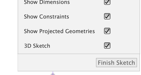
To activate 3D sketching in Fusion 360, we will activate the feature from the sketch pallet. It is a checkbox option at the bottom of the pallet labeled “3D”.
3D sketching allows you to draw lines, circles and splines anywhere within the workspace. This is what makes this feature a little bit challenging to work with because we are not confined to a two axis or two dimensional surface.
The way we are going to use it will be fairly straightforward. Once you have 3D sketch enabled, select “Point” from the create tab. This will allow us to create a point on our current sketch that is not on the same plane as the stabilizer cross. You will notice as you move your cursor over other sketches the cursor will snap to a line or a point. You will know that it is snapped because it will turn into an “X”. Move your cursor to the widest point of the former where we created a construction line. Once the cursor has snapped click to add a point.
Having this point will now allow us to create a construction line from the leading point of the stabilizer across to the widest point of our fuselage former. We will repeat this, however, we will use the top and bottom edge of our cross and also snap them to the widest point of our fuselage former.
These construction lines will serve as guides when we begin working on the formers for the empennage.
Fuselage Surface Guide Rings
The construction lines that we created, from the horizontal stabilizer across to the widest point of our fuselage, is now going to serve as the outermost lateral reference point for the surface guides.
There are 5 key ring positions that we need to create for these sketch guides:
The fairing guide ring;
halfway point between the leading edge of the stab and fairing guide ring;
forward edge ring of the horizontal stabilizer cross;
vertical cross points ring of the horizontal stabilizer;
rear point ring of the horizontal stabilizer cross,

Wingbox Fairing
To create a realistic looking fairing, our transition between the wing box to the fuselage needs to be lofted separately from the rest of the body. We want to ensure our transitions are nice and smooth. Attempting to create a single loft for this complex of a surface won’t yield the results we need.
To create the fairing, we will need to add several sketch lines from the bottom of the fuselage around to the widest lateral point. Add them in several key places as shown in the images here.
Horizontal and Vertical Stabilizer Airfoils
In the Wing Design tutorials, we used a Fusion 360 add in called “Airfoil DAT to Spine”. In this tutorial, we will learn an alternative way of adding airfoils to your design using a canvas.
We need to select airfoils which are symmetrical. It is especially crucial that the Fin has a symmetrical airfoil to prevent unwanted yaw. Some aircraft such as single engine airplanes may not use airfoils that are symmetrical to counteract P-Factor. For this example, we will not go into detail as to when or why we would use non symmetrical airfoils.
Vertical Stabilizer
I will be using the NACA 0012 AIRFOIL for the vertical stabilizer as it has a max thickness of 12% at 30% chord and 0% camber. This will match up nicely with the Boeing 777 tail section we are modeling in this tutorial. You may want to explore other airfoils for your model which may provide a more appropriate fit for your design.
Again, this is a different method of adding an airfoil than what we did in the wing design tutorial. Either method will work.
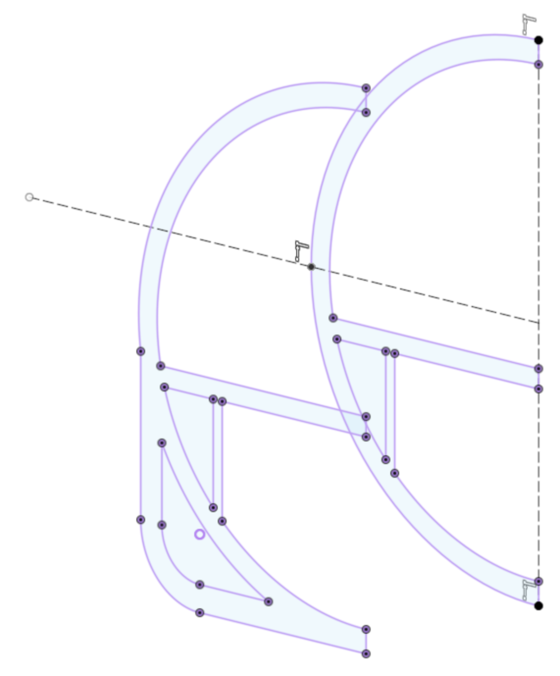
To begin, capture a screenshot of the airfoil you are wanting to use and save the file to your computer. Then we will create a construction plane, however, this time we will be creating it in a different way. We are going to use the “Plane Along and Axis” tool from the construction tab’s drop-down menu.
Once you have it active, you will select a point on the top spine sketch which is at the center point between the leading and trailing edge of the tail fin and rudder. You will notice that the construction plane will be added perpendicular to the spine. Accept it by pressing the enter key.
Find the construction plane in your components browser tree, rename it and then press the M key.
Important: Do not press the M key (or select move) after directly clicking on the actual construction plane. Doing so will position your point of origin on the plane at the point where you last clicked. We need to rotate the canvas from the exact center-point. To accomplish this click the construction plane in the browser then press the M key.
The triad movement tools will appear right in the center of the construction plane. You will want to rotate that canvas exactly 90°. This will ensure that it is positioned perfectly at the highest point of the arching spine.
Now that we have this in place, we will use the canvas tool to place our airfoil image. Position, rotate and scale the image so that it is perfectly positioned on the center line. Once positioned, we need to create a new sketch on this construction plane and project the top spine onto it. Then using the Fit Point Spine tool, trace the starboard side of the airfoil. Be sure to snap to the center line at the leading and trailing edges. Finally we need to orient the spline handles at the leading edge to be perpendicular to the spine.
Duplicate Semi Fin Airfoil
From the component tree, select the airfoil sketch then press the M key for move. In the move pallet make sure that you have the copy check box marked. This will create a replica of our semi fin airfoil.
Position your workspace so that you have the profile view and profile diagram perfectly placed on your screen. Then move the airfoil up to the top of the tail fin just below the point where the leading edge arches to the top edge of the fin. Be careful not to accidentally move the airfoil on the X axis, as this will cause a crooked tail. Press enter to accept the new position.
Since we have a copy of the first airfoil, the scale is obviously not correct for the top. While still in the top airfoil sketch, select the “Sketch Scale” tool from the modify tab. Using that tool adjust the scale and position of the airfoil. Again, be very careful not to shift the position of the half airfoil on the X axis.
Horizontal Stabilizer
Much like the wing, we will be adding airfoils at the root and tip of the horizontal stabilizers. You may choose to use the Airfoil DAT to Spline Add-In or you may choose to use the trace method we just used to create the fin airfoil.
Start by activating the construction plane we used to create the “horizontal stabilizer cross” sketch. I will be using the tracing method for this tutorial to show the contrast between these two methods. You will quickly see why the Add-In has it’s advantages when it comes to scaling our airfoil sketch.
Begin by using the canvas tool to place the airfoil diagram onto the H-stab construction plane. Scale and position the diagram where the stabilizer will be attached to the fuselage.
Before starting the sketch, project the lateral construction line of the cross onto our sketch. This will ensure we place the airfoil exactly on top of the flattest surface of our airframe.
Like before, trace half of the airfoil, then use the sketch mirror tool to complete the opposing side. Doing it this way will guarantee our airfoil is symmetrical.
Note: This method may not be ideal if you are wanting to have a perfect match to the airfoil you have selected. In which case you will want to use the Add In as demonstrated in the wing design airfoils tutorial, see video at 10:37.
You may be tempted to create a copy and move the root airfoil to the tip and then resize it. There is a problem with this approach. When you scale the airfoil, any imperfections you have in your sketch will cause distortions in your spline. This is one of the main reasons using the trace method is not ideal and using the add in is more accurate, even if it’s more steps.
We’ll continue with the tracing method and create a construction plane at the tip of the H-stab. Make sure that you place the plane just before the outer edge since this is where the leading edge arches around to the stabilizers tip.
Follow the same steps we used to create the root airfoil.
Lofting the Airframe Skin
Congratulations, you’ve sketched the entire starboard side and empennage! We can now get to the fun part which is lofting the airframe’s skin. We will do this for each individual component:
The fuselage;
vertical stabilizer;
horizontal stabilizer;
and wingbox fairing.
I am going to assume that you have completed the tutorial where we modeled the nose of an airplane. Using this same process we will loft the empennage airframe first.
To ensure we have nice transitions, we will be using the guide rings as our profiles and the spines as our rails. Make sure you don’t include the projected former which contains the wingbox. Including in in this loft will result in a slightly deformed surface.
Next, loft the horizontal and vertical stabilizers. Note, we are only lofting half of the V-Stab.
Finally loft the wing box fairing.
Wrapping Things up with Formers, Bulkheads, and Ribs
We’ve covered a lot of ground in this tutorial. The final step is adding in the structural components for our airplane. We need to position all of our formers, bulkheads, and ribs within the vertical and horizontal stabilizers.
We will start with placing our formers and bulkheads. If you have completed the other tutorials where we added formers, you will know that we start with placing surfaces and then using the pattern tool to duplicate each of them.
The empennage is a little bit different because we need to take into consideration the joining components; the V & H-stabs. For this reason we need to be more thoughtful about how many formers and bulkheads we place, and how we will pass through the control surface loads into the fuselage.
The way you ultimately want to construct your RC model airplane has a strong barring on how you structure the internals of this section. There are a few decisions you will need to make;
Will your H-Stabs be fixed or do you want them to be removable?
Will your V-Stab be fixed to the fuse or do you also want it to be removable?
Is your empennage fixed to the wingbox section of the plane or is it also removable?
As you can see, these are decisions that will have significant impacts on how you decide to design. Watch the attached video tutorial for inspiration.
Conclusion
In this tutorial we completed the design of the primary structure of our model airplane by adding the empennage, also called the tail, of our model airplane. By strategically going step by step, using Fusion 360 incredibly versatile sketch tools, we were able to define the key structural splines which became the bases for our fuselage skin. As we have with previous design tutorials, we worked on the starboard side of the aircraft. Since the plane we are designing is symmetrical, we can save time by not modeling both sides of the airplane. We can now simply use the mirror tool to reflect the starboard side into a port side replica. We finished off the tutorial by adding in the structural components of the body.
Episode Outline
0:00 Introduction and thanks to Tippers
2:46 Projecting Fuselage to New Tail Component
6:31 Sketch Airframe Center Spine and Keel
10:41 Horizontal Stabilizer Mounting Cross
22:11 Sketch Airframe Profiles
37:51 Wing Trailing Edge Fairings
47:12 Horizontal and Vertical Stabilizer Airfoils
1:03:45 Loft the Airframe Skin
1:10:18 Add Bulkhead and Former Surfaces
1:15:55 Close - Request a Video Topic