
Part 2: Design a RC Airplane in Fusion 360 (Spars & Ribs)

Episode 3 - How To Create Wing Spars and Ribs
In this episode, we will continue from where we left off in part 1. We will cover some basic organizational tasks, creating wing spars, wing ribs, and ensure we have the perfect shape for all of the interior parts of our airplane’s wing. If you have not completed the work from that episode yet, I recommend you go back to “How to Design a RC Wing in Fusion 360” part 1 to begin. This guide is to supplement the included YouTube video tutorial.
The work that we will be doing in this tutorial is geared towards modelers who will be building their airplane out of word or foam board, then cutting the pieces out with a CNC machine, laser cutter, or hand cutting from printed diagrams. 3D printing involves other steps which are not covered here, however, many of the design concepts are the same.
First, Organizing Our Fusion 360 Workspace
Before we begin, now is a good time to start structuring and organizing our model. In this tutorial we will be creating a lot of new parts and our browser will quickly get unwieldy and slow down the design process. To save us time and headaches down the road, we will start creating components and moving our existing bodies into those. I’d recommend not skipping over this bit of housekeeping, you'll be happy that you did.
What are Components in Fusion 360?
Fusion 360 components is an organizational tool used for grouping bodies together into logical collections. Components help you better understand the model you are working on and give you the ability to easily isolate components from the rest of your model, create copies and many other benefits.
Now that we have a general understanding of what components are in F360, let’s start creating a few empty components to set up our structure. We will create the following components.
Fuselage
Spars
Ribs (Interior)
Ribs (Trailing)
Ribs (Leading)
How to Create a New Component in Fusion 360
To create a new component in Fusion 360, make sure the Components Browser is visible. Right click the root component, or a child component. From the expanded menu, select “New Component”. You will be presented with the new Component Options Palette. Select your preferred options and press ok. Your new component will appear as a child of your chosen component in the browser tree.
Now that we have our empty components created and nicely organized for our project, it’s time to move all of the Fuselage Formers we created in part one, into the currently empty Fuselage Component.
Select all of the bodies that make up the formers by holding down the shift key and selecting them, or you can click and drag across each former in the workspace. Once they are all selected, click hold one of the selected bodies and drag them into the Fuselage component. Once moved, expand the component and you should see all of the formers inside.
How to Activate Components in Fusion 360
To activate a component, hover your mouse pointer over the component you’d like to make active. A small dot (Radio Button) will appear after the component name. Simply click it and the component will become active.
The benefit of activating a component ensures all of the bodies, construction planes, sketches, forms, and surfaces you create will be added to the active component.
It’s good practice to go through this extra step to keep things nice and tidy. Keeping our workspace organized will help us better manage our design as it becomes more complex with more parts, construction planes and sketches.
Let’s Start Creating!
Create Construction Planes
Step 1 - Spar Planes
Start by activating the Spars Component to ensure everything we do will be added to that component.
As we did in Part 1, we need to set up our work space with several more construction planes. Adding construction planes will provide the foundations we need for creating the surfaces we need to begin creating templates for what will ultimately become the inside of our wing.
We will start with creating 2 construction planes where our forward spar and aft will be placed. Keep in mind, in this tutorial I am designing an airliner, which has a more complex wing structure than a straight winged aircraft.
Even though this is a more complex design, the fundamentals you will learn here will help you work through any design you choose to work on.
To create our first plane for our leading spar we will use the X Z axis origin plane to create a new construction plan. Once created move near the leading edge of the wing root.
Make sure you have your sketches turned on so that you can see where the leading edge is. Alternatively you may want to activate your footprint diagram (Canvas) and use it as a reference.

I Can’t Rotate Construction Plane in Fusion 360?
If you are unable to rotate the construction Plane for your spar and ribs, you must turn off Parametric Modeling.
To turn off parametric modeling, right click on the root component and select “Do not capture Design History” at the bottom of the pop up menu.
You should now be able to rotate canvases.
The next thing we want to do is resize the construction plane and then rotate until it is parallel with the leading edge of the wing. The last step is to make sure that the construction plane is positioned where you want the leading edge spar to be.
Moving on to the trailing edge spar, we will create another construction plane. Instead of using the X Z origin plane, we can simply use the leading edge plane as our starting point. After you have created the new plane move and rotate it to the correct angle.
In this airliner design, there is another spar where main flaps attach. Following the same process we need to create, size and position one more construction plane. If your design does not have this feature, obviously you will skip this step.
Step 2 - Rib Planes
With the spar planes in place we can move on to the ribs. The good thing about this is we only need to position 1 plane which will be used as our starting point. The quickest way to do this is to use one of the spar planes to create a new plane, then rotate it 90 degrees.
As mentioned before, some of these steps may not apply to your design. Be sure to adapt these concepts to your model as you see fit for your build.
The interior rib can be angled perpendicular to the airplane's center-line, or you may choose to place them at an angle as I am in this tutorial. This is a design decision that is up to you.
Before moving on, be sure your construction planes are in the intended components, and they are all sized in a way that makes them easy to identify in our workspace when turned on.
Create Spar Surfaces
Now comes the fun part. These steps may seem a little cumbersome at first, but I prefer doing it this way for good reason.
Why Start with Surfaces?
Early on in my design, I made the mistake of creating solid bodies and then cutting them. This resulted in chamfered and beveled edges creating a difficult situation later on down the road. For this reason, it is best to start with surfaces. They’re not solids and thus we can create bodies from them with perfectly square edges further along in the design process.
Step 1 - Create Spar Surfaces
Activate the “Spars” Component, then create a new sketch using the leading spar construction plane. Make sure you are looking at the wing from either the front view or the rear view. Then draw a square covering the entire area of the wing. Your sketch should extend past the wing root and the wing tip.
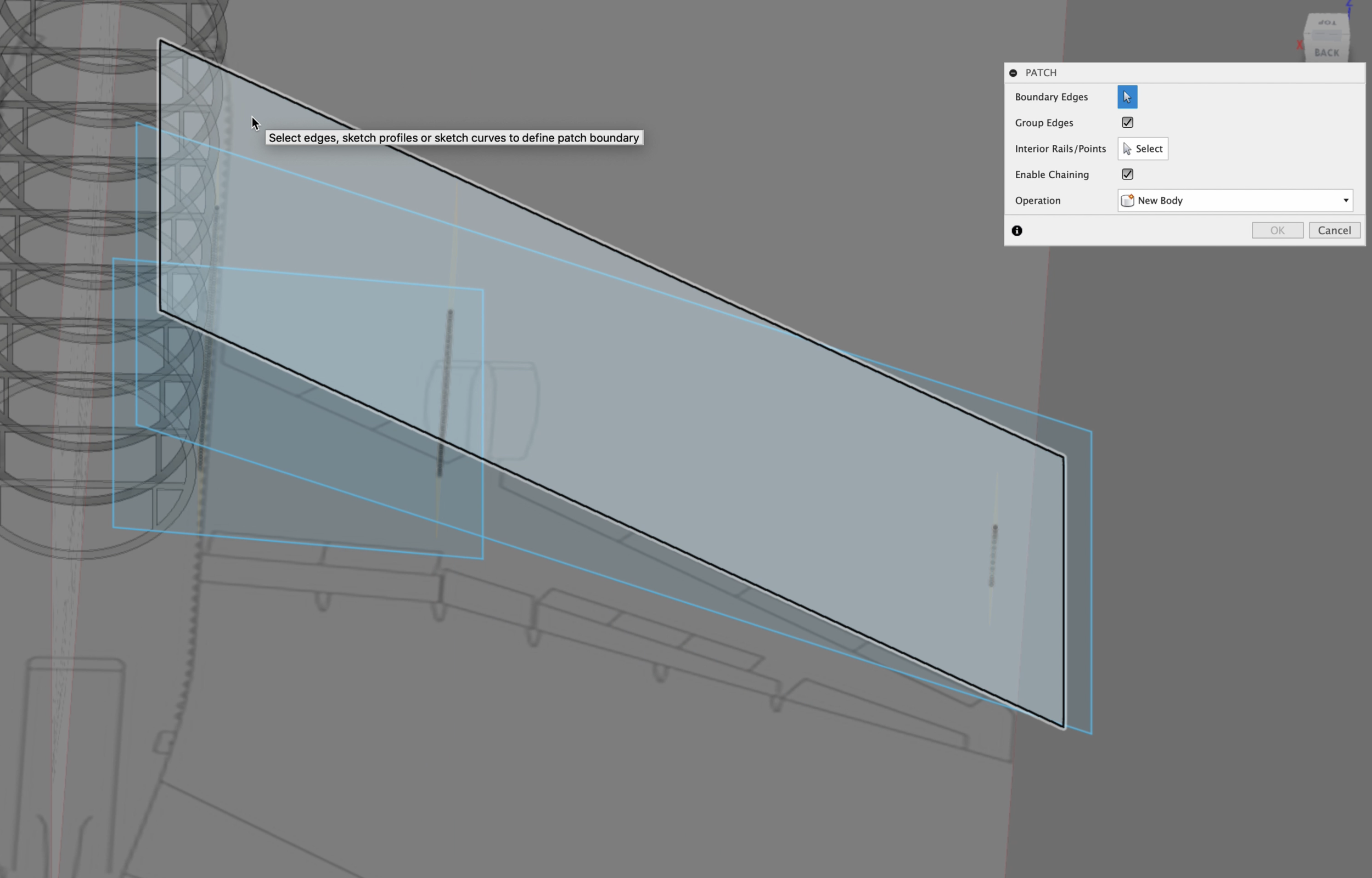
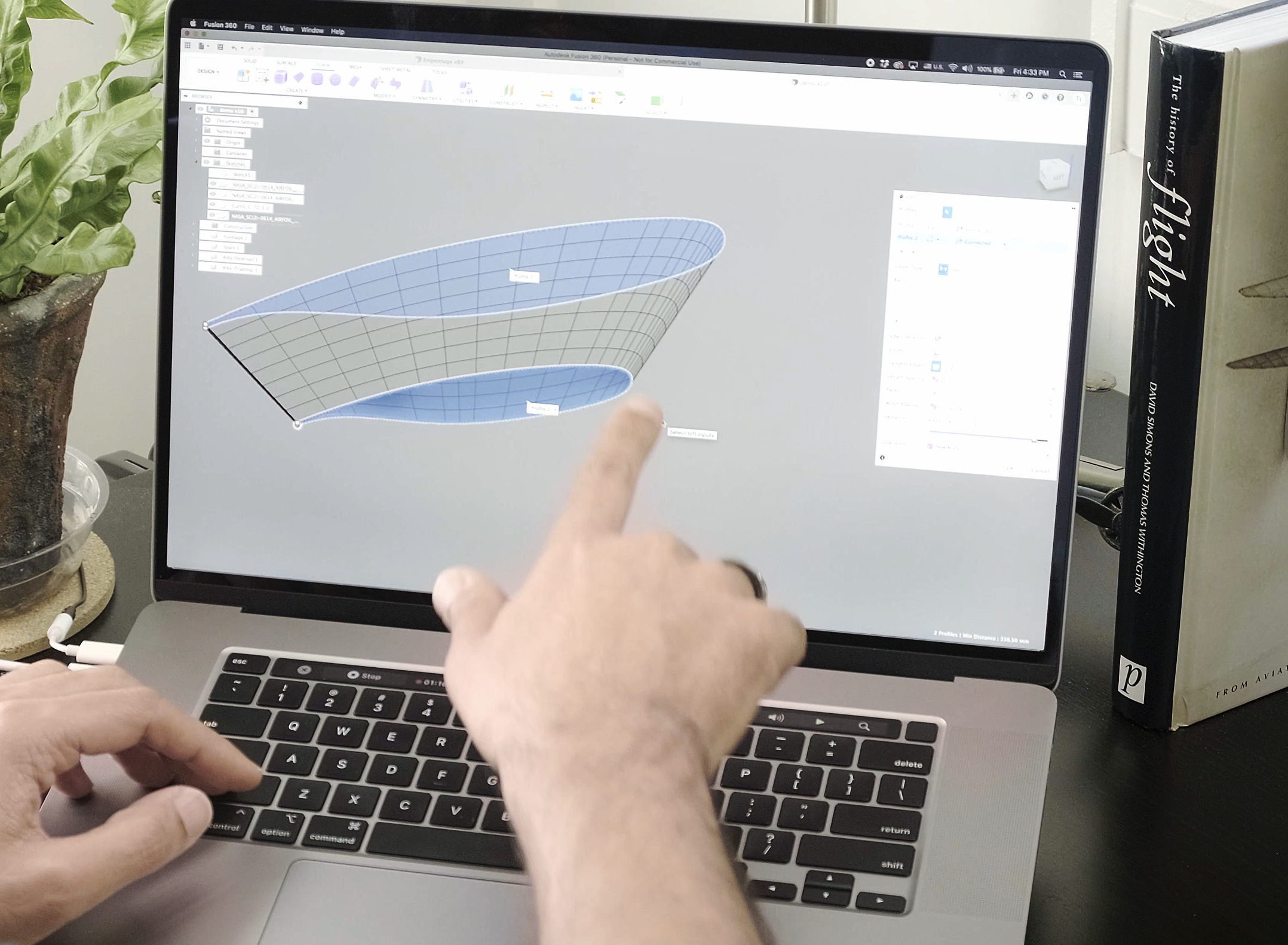
Let’s add our first surface. In the tool tape across the top of the interface, select the surface tab. This will give you the surface tools in addition to some of the other tools we’ve come accustomed to seeing. For now, thought, we are only interested in using the patch tool. Select it then select the leading edge sketch we just created.
We now have our very first surface. You’ll notice how large it is, this is exactly what we need and want. If the edges of the surface do not extend well below, above and off to the side of the wing, you will need to extend those edges.
Repeat this same step again for the trailing edge spar. If your plane also has the flap mounting spar, add it as well.
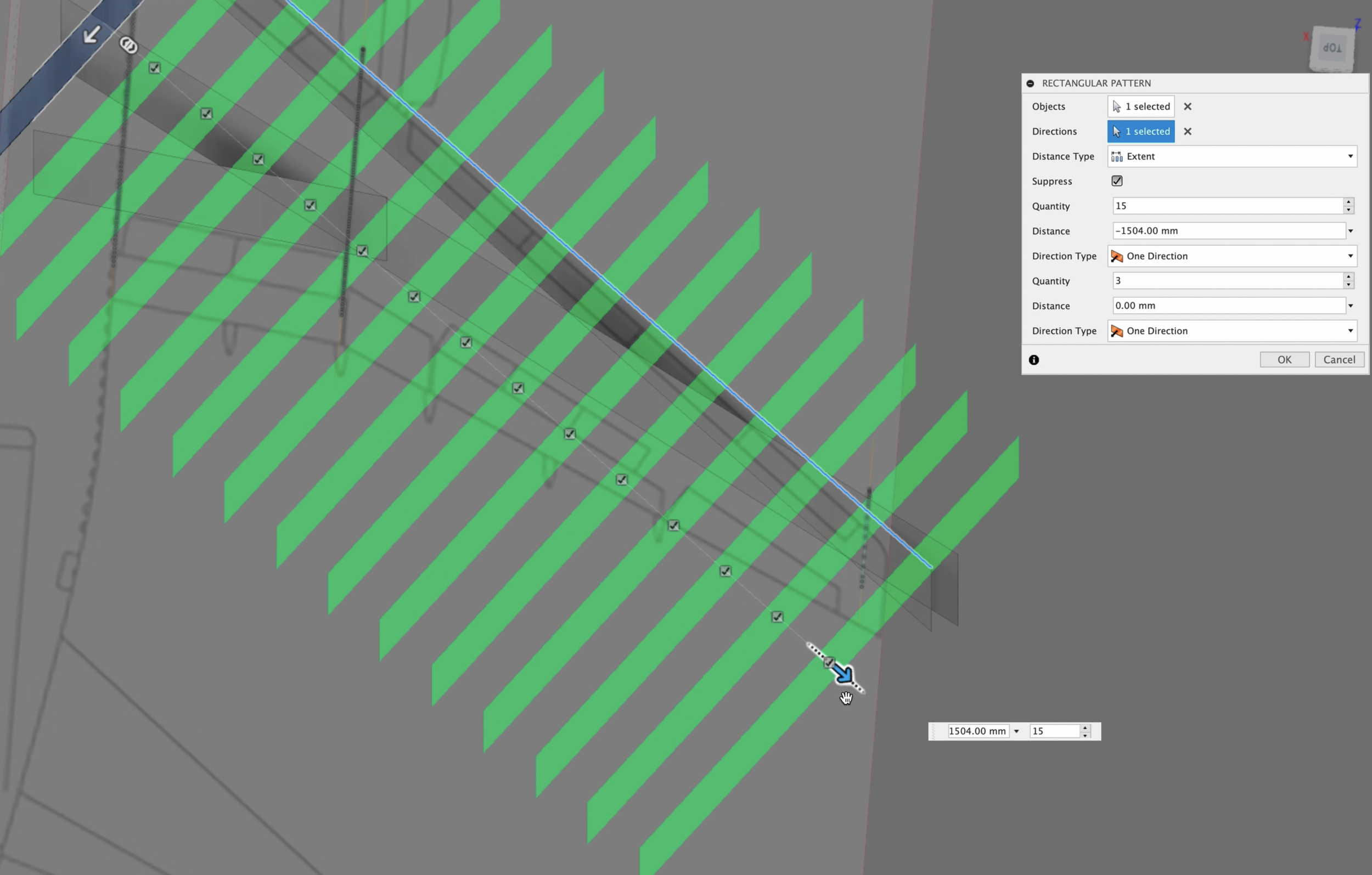
Step 2 - Create Internal Rib Surfaces
Activate the empty “Ribs (Internal)” Component and follow the same process as we did before with the spars. Double check to make sure you are in the correct component to save you the headache of hunting for surfaces later on.
Now that we have our first rib surface in place, use the pattern tool, like we learned in Episode 1 - How to start Designing an RC Airplane in Fusion 360 to create as many ribs as you need from the root to the wing tip.
Step 3 - Create Trailing Edge (Optional)
In this model, the trailing edge ribs have a different angle because of the flap gate, main and outboard flaps which move parallel to the fuselage. If your design also has this feature or design characteristic, repeat the same steps of creating surfaces as we did for the internal ribs
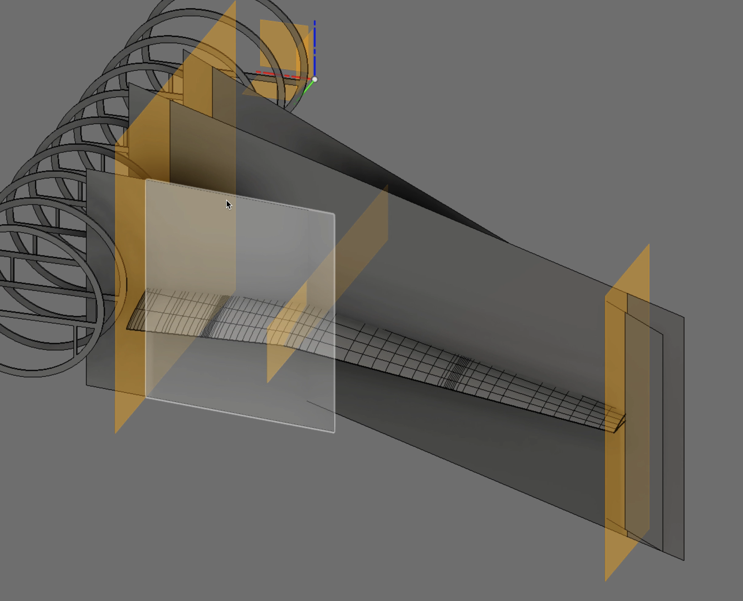
At this point we have a very crazy looking intersecting collection of surfaces. We are getting close to where the magic happens!
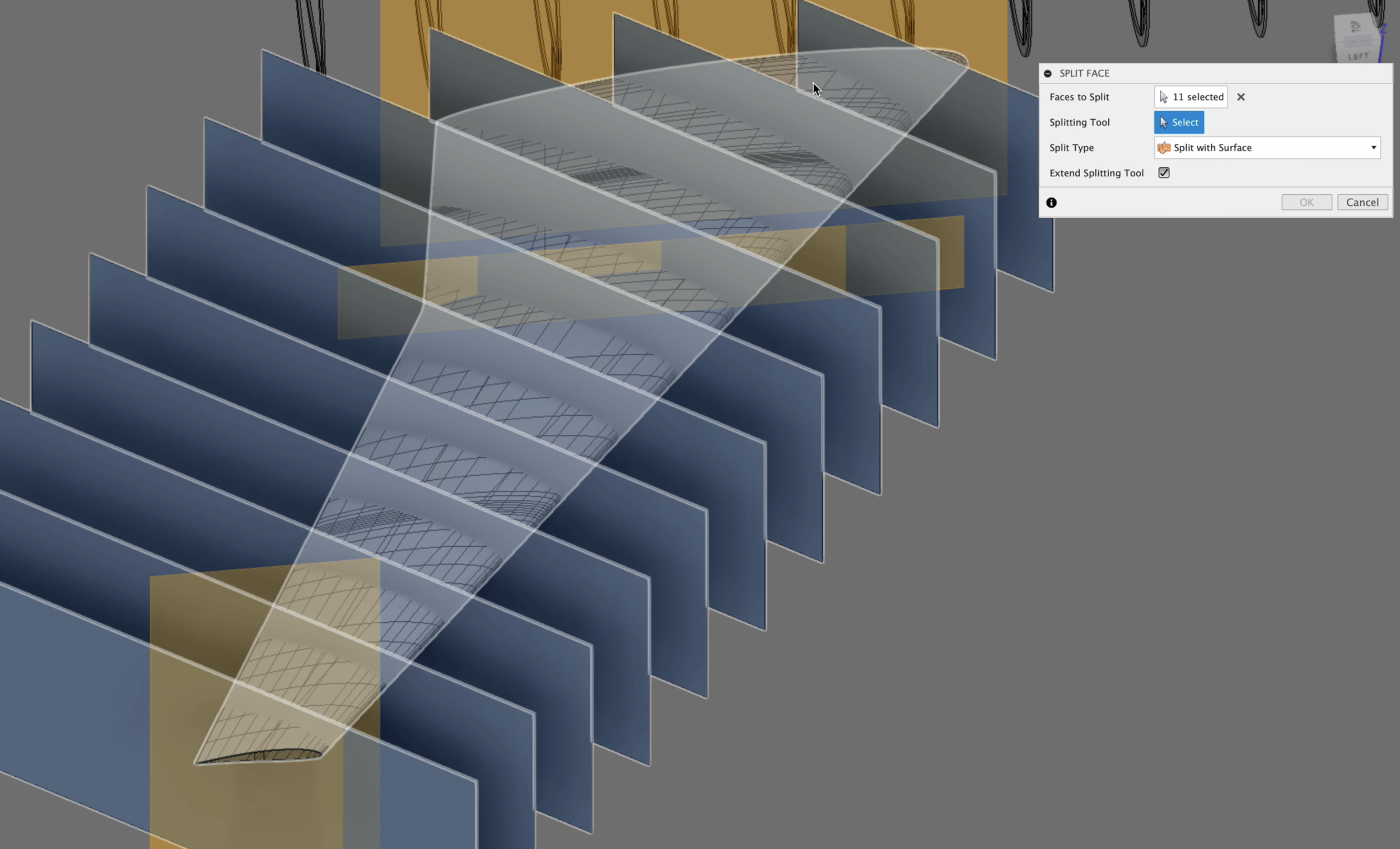
Surface Overruns
Split Overruns: In a few minutes we’ll be cutting out our ribs and spars. Currently our surfaces overrun our cutting tools, which was done purposefully. We need to make sure that our edges align perfectly for our split tool. We need to use the split tool to remove the excess surfaces. Right now we just want to remove the wing root and the wing tip overruns.
How to Split Faces in Fusion 360
To split faces or surfaces in Fusion 360, the split tool is used. It is important that the tool you select completely intersects the entire face you are wanting to cut. First select the split tool from the modify tab. Next select the face(s) you are wanting to cut or split, then select the Splitting tool(s). Finally press OK in the Spit Body Pallet.
Lofts
It’s now time to create a loft using our airfoils.
In this model, there is a direction change on the trailing edge. Because of this we need to create a duplicate of our center airfoil, and move it a fraction of a millimeter. The reason for this is to prevent the loft tool from softening or smoothing the hard angel change. Later on we will merge our lofts together.
How to Create a Loft in Fusion 360
To create a loft in Fusion 360, use the loft too found in the Solid, Surface, and Form tabs. Select a sketch or face edge and then select another sketch or face edge. The loft tool will calculate the most smooth transition between the edges you’ve selected.
Lofts in Fusion 360 are a very handy tool and take the manual guesswork out of shaping and sculpting our model. There are three variations of lofts in Fusion 360. And their use depends on the task at hand. In this tutorial we will be using the “Form” loft.
Start by activating the “Loft” tool under the “Form” tabs, then select the wing root airfoil sketch, it will highlight. Then select the center airfoil sketch closest to the root. Remember we created a duplicate that is very close to the original center airfoil. We need to make sure that we don’t select the outer airfoil. Once the two sketches have been selected you will see the loft appear.
There are a few adjustments we need to make in the loft pallet. First make sure that the “Width Spacing” drop down menu is set to “Curvature”. The default is Uniform, which we do not want. You will notice the loft splines will change and form a smother leading edge.
You may also select “Curvature” for the “Length Spacing”, however, it is not as important as the width spacing.
Then press OK.
Merging Lofted Surfaces
You will notice in your Component Browser tree two components were created. If you only have one, then this next part you can skip.
When we created the loft, the trailing edge will not be in a condition that will allow us to use the lofted surface as a splitting tool. For this reason we need to delete the trailing edge faces and then merge the edges.
To do this we need to zoom in very closely to the trailing edge. You will notice several edges running horizontally. We need to delete these.
Once deleted, we can merge the two form bodies together.
How to merge Faces in Fusion 360
Select the “Merge Edge” tool, which will activate the Edge Merge Palette. Press the ‘Edge Group 1” button, then double click on the upper trailing edge. It will highlight in blue indication the entire edge has been selected. In the palette, select the “Edge Group 2” button and then double tap the lower edge. Again, it will highlight the entire edge in blue. Select the “Maintain Crease Edge” checkbox if you would like to have a hard edge. Press OK. You should now only have one Form Body in your Component Browser.
Next we want to repeat this process, this time for the outer wing airfoils. Once this is done we will need to merge the two bodies together to create a singular airfoil body.
Zoom in as close as you can to see the gap between the two Form Bodies. Once you can see them. Use the “Merge Edge” tool again to join them.
How to Select all edges in Fusion 360
To select all edges in Fusion 360 double tap an edge segment which contains all of the segments you would like to select. Once you’ve double tapped on an edge, all edge segments chained together will be highlighted in blue indicating they are all selected.
You will do this for both airfoil surfaces that were created.

Cut out Internal Structures
Our workspace, at this point, looks like a hot mess of flat surfaces crisscrossing each other. It doesn’t resemble anything that remotely looks like a wing. Don’t worry, we’re about to create the foundations for our ribs and spars.
This is where the magic happens. Think of the surfaces as sheets of aluminum, and our cutting tools are like die presses punching out the desired shapes from the aluminum sheets. We will be doing the same thing here, just in a virtual sense.
Cut The Spar Surfaces
Select all of the spars, you can do this one of two ways.
In the workspace angle your viewing angle so that you can see all of the surfaces. Then click and drag across of the them. They will turn blue when they have been selected. You will notice they are all selected in the component browser.
or you can select all of the surfaces in the Component Browser. This method can be a little more tedious if you have not been naming and organizing your bodies and components. If you have done a good job of keeping everything names, hold down the control or option key and select all of the surface bodies.
IMPORTANT: If any of your surfaces are not perfectly aligned to the wing root edges or your surfaces do not fully extend the top and bottom of the wing, you will get errors. If this happens, make all of the adjustments to the surfaces so this next step will work as intended.
Ready to start cutting? Me too, Let’s do this.
In the “Forms” tab, select the “Split Body” or “Split Face” tool. With our surfaces selected, select the “Tool” option from the Split Palette and select the lofted wing body. The wing will turn red indicating it is now the cutting tool. Click OK when done.
Turn the visibility of the lofted wing off. You should now see all of the airfoils cut into the surfaces. Now just select the wasted portion and delete each one.
Voilà You Have Spar Templates!
This technique can now be repeated for your ribs.
Make Solid Bodies From Surface Templates
It seems like we’ve done a whole lot of work to get to this part, but now we are guaranteed to have perfect templates needed to extract our individual parts with total precision.
This final step in creating our solid bodies will be a bit repetitive but you’re are almost done.
Select a surface template’s face, then press the letter “e” on your keyboard to activate the “Extrude” tool. Then pull in the direction, which makes sense for your design, the desired thickness. It should match your intended thickness of the material you will be using.
Conclusion
In this episode we covered a lot of ground and make a lot of new parts and pieces for our wing. We started the process of organizing and structuring our components so that we can easily manage and find what we are looking for as the design become more complex. Then we used construction planes as our foundations for creating positioned surfaces.
The surfaces were used to cut our templates for our wing’s spars and ribs. Once we had those we were able to use the surfaces to extrude actual solid bodies.
We also learned the basics of creating form lofts and how to merge multiple lofts together to from one solid piece which became our template cutting tool.
If you have any questions or need additional help, please contact me through the website or DM me on any of the social media accounts I have listed here.
Until next time, happy modeling.
Episode Outline
0:00 Introduction & Summary
0:50 What are Components in Fusion 360?
1:36 Create Components
4:22 Spar Construction Planes
9:22 Spar Surfaces
12:18 Base Rib Construction Plane
14:48 Rib Surfaces
19:08 Setting Up For Loft
20:25 Duplicate Center Airfoil Sketch
22:16 Create First Loft of Wing
27:00 Merge Separated Wing Lofted Skins
28:39 Trimming Excess Surfaces
31:43 Cutting Out Spar Templates
33:04 Cutting Out Rib Templates
40:02 Extrude Spars & Ribs From Templates
42:20 Thank You
42:44 Bloopers